Ford Galaxy / Ford S-MAX. Manual - part 398
 

  Index      Ford     Ford Galaxy / Ford S-MAX - service repair manual 2006 year


Search            


Content   ..  396  397  398  399   ..


Ford Galaxy / Ford S-MAX. Manual - part 398


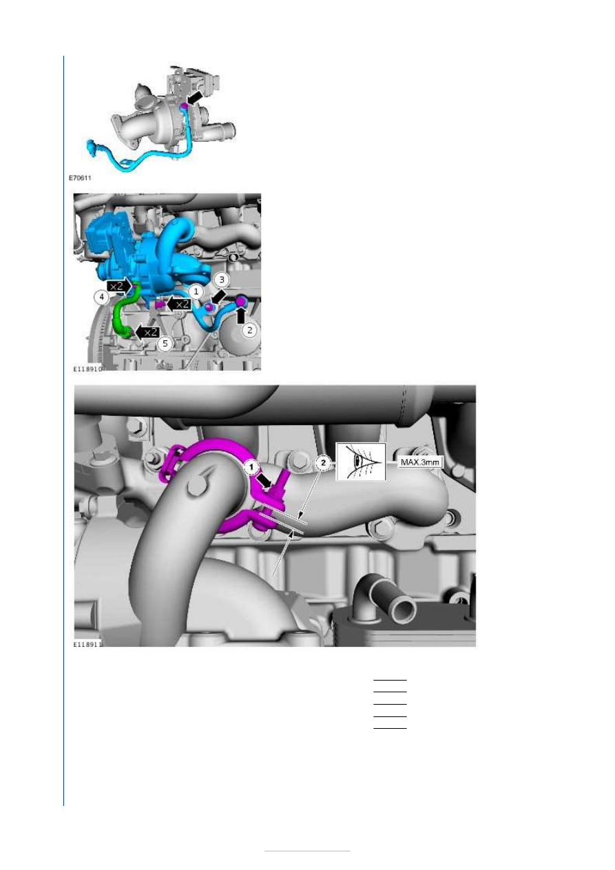
2.

NOTE: Only tighten the nuts and bolts finger tight at 
this stage. 

3.

NOTE: 
Make sure 
that a new 
component 
is installed.
NOTE: 
Make sure 
that the 
clamp is 
installed to 
the same 
orientation 
as when 
removed.

1. Torque: 

5 Nm

4.   

1. Torque: 25 Nm 
2. Torque: 35 Nm 
3. Torque: 23 Nm 
4. Torque: 10 Nm 
5. Torque: 10 Nm 


5.

CAUTION: Make sure that the inside of the pipe 

ends are clean and free of oil residue. 

6. Install the following items: 

Refer to: 

Catalytic Converter

 (309-00D Exhaust 

System - 1.8L Duratorq-TDCi (74kW/100PS) -
Lynx/1.8L Duratorq-TDCi (92kW/125PS) - Lynx, 
Removal and Installation). 
Refer to: 

Air Cleaner

 (303-12D Intake Air 

Distribution and Filtering - 1.8L Duratorq-TDCi 
(74kW/100PS) - Lynx/1.8L Duratorq-TDCi 
(92kW/125PS) - Lynx, Removal and Installation).


Fuel Charging and Controls - 
Turbocharger - 2.0L Duratorq-TDCi 
(85kW/115PS) - DW/2.0L Duratorq-TDCi 
(100kW/136PS) - DW/2.0L Duratorq-
TDCi (103kW/140PS) - DW, Emission 
Requirements: Stage IV - Turbocharger

S-MAX/Galaxy 2006.5 (02/2006-)


Print


Description and Operation 

Turbocharger with variable turbine geometry 


Description 

Turbocharger position sensor 

Turbocharger housing 

Seal 

Connector 

Connecting hose - oil return 

Bracket 

Banjo bolt 

Oil line 

Banjo bolt 

To ensure an optimum torque curve, a Garrett turbocharger with variable turbine geometry 
is used. 

The movable guide vanes on the turbine wheel are adjusted by the turbocharger vacuum 
canister by means of a connecting rod. 

A position sensor is located centrally on the turbocharger vacuum canister; this forwards 
the position of the guide vanes to the powertrain control module (PCM) as an input 
variable. 

The vacuum to the turbocharger vacuum canister is metered by the boost control solenoid 
valve. The boost control solenoid valve is controlled by the PCM . 

The bearings of the turbocharger are lubricated by the engine's oil circuit via a rigid oil pipe. 

Item

1

2

3

4

5

6

7

8

9


Part Number

-

-

-

-

-

-

-

-

-

Fuel Charging and Controls - 
Turbocharger - 2.0L Duratorq-TDCi 
(85kW/115PS) - DW/2.0L Duratorq-TDCi 
(100kW/136PS) - DW/2.0L Duratorq-
TDCi (103kW/140PS) - DW, Emission 
Requirements: Stage IV - Turbocharger

S-MAX/Galaxy 2006.5 (02/2006-)


Print


Diagnosis and Testing 

Special Tool(s) 

General Equipment 

Inspection and Verification 

NOTE: It is normal for a small amount of combustion gas to pass into the crankcase. This 
gas is scavenged into the air intake system through the positive crankcase ventilation 
(PCV) system, which incorporates an oil separator. Some engine oil, in the form of a 
vapor is carried into the air intake system with the blow-by gases (this engine oil also 
contributes to valve seat durability). This means that oil will collect inside the air intake 
components and the turbocharger. This is not an indication that the turbocharger oil seal 
has failed. The turbocharger oil seal will not fail unless the bearings fail first, which will 
cause the turbocharger to become noisy or seize. Do not install a new turbocharger due 
to oil inside the turbocharger or the air intake components. If a leak is detected in the oil 
supply or return tubes or connections, locate and rectify the source. Do not install a new 
turbocharger due to an oil leak. 

1. 1. Verify the customer concern. 

2. 2. Visually inspect for obvious signs of mechanical or electrical damage. 

Visual Inspection Chart 

3. 3. If an obvious cause for an observed or reported concern is found, correct the cause 

Hand Vacuum/Pressure Pump 

416 - D001 (23 - 036A) 

Fuel Pressure Gauge 

310-053 (23-046) 

Worldwide Diagnostic System (WDS) (418-
F224)

Mechanical

Electrical

Oil leak(s)  

Air cleaner element  

Air cleaner outlet pipe  

Air cleaner intake pipe  

Turbocharger oil supply or oil return tube  

Turbocharger intake pipe  

Turbocharger vacuum diaphragm unit  

Turbocharger housing  

Charge air cooler  

Charge air cooler intake pipe and hose(s)  

Charge air cooler outlet pipe and hose(s) 

Wiring harness  

Vane adjustment solenoid valve  

PCM 


Content   ..  396  397  398  399   ..