Ford Galaxy / Ford S-MAX. Manual - part 396
 

  Index      Ford     Ford Galaxy / Ford S-MAX - service repair manual 2006 year


Search            


Content   ..  394  395  396  397   ..


Ford Galaxy / Ford S-MAX. Manual - part 396


Fuel Charging and Controls - 
Turbocharger - 1.8L Duratorq-TDCi 
(74kW/100PS) - Lynx/1.8L Duratorq-
TDCi (92kW/125PS) - Lynx - 
Turbocharger

S-MAX/Galaxy 2006.5 (02/2006-)


Print


Description and Operation 

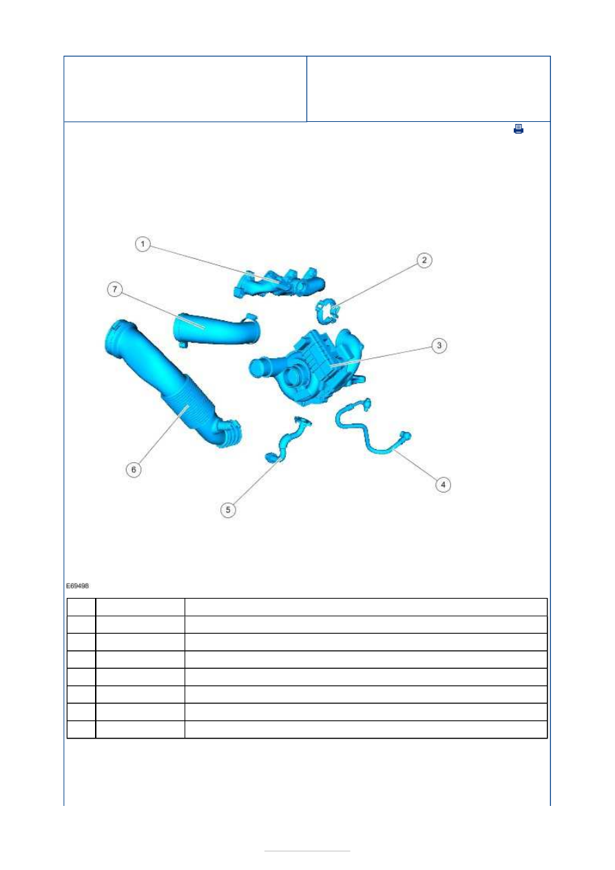
Turbocharger - General Overveiw 


Description 

Exhaust manifold 

Turbocharger retaining clamp 

Turbocharger 

Turbocharger oil supply pipe 

Turbocharger oil return pipe 

Turbocharger inlet hose 

Charge air cooler inlet pipe 

Variable Vane Turbocharger 

The engine is fitted with an electronically controlled variable vane turbocharger. The 
turbocharger is fixed to the exhaust manifold by a retaining clamp. The turbocharger 
consists of two elements, a turbine and a compressor both installed on a single shaft. 

Item

1

2

3

4

5

6

7


Part Number

-

-

-

-

-

-

-

The turbocharger bearings are supplied with oil from the engine. 

The turbine uses the flow of the exhaust gas to drive the compressor. The compressor 
draws air through the air cleaner and forces it into the intake manifold. 

The turbocharger is designed to improve engine induction and engine performance. The list 
below details the possible concerns relating to turbocharger performance. 

High engine speed produces excessive turbine speed and therefore creates excessive 
turbocharger boost pressure.  
Low engine speed does not produce sufficient turbine speed and therefore not enough 
turbocharger boost pressure is achieved. 

The turbocharger does not have a wastegate control valve. Instead, it has variable 
turbocharger vanes which are located in the turbocharger turbine housing and these direct 
the exhaust gas flow into the turbocharger turbine. The turbocharger vanes act as the 
control for the turbocharger boost pressure. 

The turbocharger produces its full turbocharger boost pressure over the entire engine speed 
range, not just at high engine speed. This is achieved through the adjustment of the vanes 
and the resulting change in the flow of the exhaust gas. 

The speed of the exhaust gas flow within the turbocharger is increased independent of 
engine speed by varying the intake cross section in front of the turbocharger turbine. This 
is achieved by adjusting the angle of the vanes controlling the exhaust gas flow into the 
turbocharger turbine and this drives the turbocharger turbine faster. The higher 
turbocharger speed produces a high turbocharger boost pressure at all engine speeds. 

The powertrain control module (PCM) controls the turbocharger vanes by means of an 
electronic vane adjustment solenoid attached to the turbocharger. 

Regulation at Low Engine Speed 

At low engine speeds the PCM operates the vane adjustment solenoid. The vane adjustment 
solenoid moves the adjusting ring so that the vanes are set at a shallow angle. The shallow 
intake cross section this creates for the stream of exhaust gas allows the turbocharger 
boost pressure to build up rapidly and easily at low engine speeds. 

Regulation at Moderate Engine Speed 

As the engine speed increases and the quantity of exhaust gas increases, the vane 
adjustment solenoid moves the adjusting ring so that the vanes are set at a steeper angle. 
The steeper angle opens the intake cross section effectively reducing the gas flow and 
turbine speed, while maintaining constant turbocharger boost pressure. 

Regulation at Maximum Engine Speed 

As the engine speed increases the intake cross section in front of the turbocharger turbine 
is continuously enlarged. The turbine speed and hence the quantity of the air supplied to 
the engine, is adjusted to suit the engine speed. This means that the turbocharger boost 
pressure remains optimized over all engine speeds. 

The maximum position of the turbocharger vanes (maximum opening cross section) is also 
an emergency position, in the event of an electrical concern. This lowers the chance of 
engine damage due to excessive boost in the event of a turbocharger control concern. 

Fuel Charging and Controls - 
Turbocharger - 1.8L Duratorq-TDCi 
(74kW/100PS) - Lynx/1.8L Duratorq-
TDCi (92kW/125PS) - Lynx - 
Turbocharger

S-MAX/Galaxy 2006.5 (02/2006-)


Print


Diagnosis and Testing 

General Equipment 

Inspection and Verification 

NOTE: It is normal for a small amount of combustion gas to pass into the crankcase. This 
gas is scavenged into the air intake system through the positive crankcase ventilation 
(PCV) system, which incorporates an oil separator. Some engine oil, in the form of a 
vapor is carried into the air intake system with the blow-by gases (this engine oil also 
contributes to valve seat durability). This means that oil will collect inside the air intake 
components and the turbocharger. This is not an indication that the turbocharger oil seal 
has failed. The turbocharger oil seal will not fail unless the bearings fail first, which will 
cause the turbocharger to become noisy or seize. Do not install a new turbocharger due 
to oil inside the turbocharger or the air intake components. If a leak is detected in the oil 
supply or return tubes or connections, locate and rectify the source. Do not install a new 
turbocharger due to an oil leak. 

1. 1. Verify the customer concern. 

2. 2. Visually inspect for obvious signs of mechanical or electrical damage. 

Visual Inspection Chart 

3. 3. If an obvious cause for an observed or reported concern is found, correct the cause 

(if possible) before proceeding to the next step. 

4. 4. If the cause is not visually evident, verify the symptom and refer to the Symptom 

Chart. 

Symptom Chart 

Symptom Chart 

Worldwide Diagnostic System (WDS)

Mechanical

Electrical

Oil leak(s)  

Air cleaner element  

Air cleaner outlet pipe  

Air cleaner intake pipe  

Turbocharger oil supply pipe  
Turbocharger oil return tube  

Turbocharger intake pipe  

Turbocharger housing  

Charge air cooler  

Charge air cooler intake pipe and hose(s)  

Charge air cooler outlet pipe and hose(s) 

Wiring harness  

Turbocharger electronic actuator  

PCM 

Symptom

Possible Sources

Action

Blue smoke with 
excessive 
turbocharger noise

Turbocharger 

compressor rubbing on 
housing walls. 

Turbocharger turbine 

rubbing on housing 

*

*

GO to Pinpoint Test 

A. 


*

Pinpoint Tests 

walls. 

Turbocharger bearings 

and oil seal(s). 

Turbocharger oil 

supply tube blocked or 
damaged. 

*

*

Blue smoke without 
excessive 
turbocharger noise

Turbocharger oil return 

tube blocked or 
damaged. 

*

GO to Pinpoint Test 

B. 


*

Poor engine 
performance 

Charge air cooler 

system. 

*

CHECK the charge air cooler, charge air 

cooler pipes and charge air cooler hoses for 
leaks and obstructions. REPAIR as 
necessary. 

*

Air cleaner intake pipe. 

*

CHECK the air cleaner intake pipe for 

obstruction. REPAIR the necessary. 

*

Turbocharger 

electronic actuator. 

*

REFER to WDS. 

*

PINPOINT TEST A : BLUE SMOKE WITH EXCESSIVE TURBOCHARGER NOISE 

TEST CONDITIONS

DETAILS/RESULTS/ACTIONS

A1: INSPECT THE TURBOCHARGER ROTOR VANES FOR DAMAGE

Location of the engine upper cover retaining clips.  

CAUTION: Care must be taken when releasing 

the fourth retaining clip and maneuvering the engine 
upper cover past the manifold absolute pressure 
(MAP) sensor. Failure to follow this instruction may 
result in damage to the MAP sensor. 
NOTE: Only remove and install the engine upper 
cover in the sequence shown. 

Remove the engine upper cover. 

Detach the turbocharger intake pipe and position it 
to one side. 

Inspect the turbocharger rotor vanes for damage. 


Content   ..  394  395  396  397   ..