Ford Galaxy / Ford S-MAX. Manual - part 346
 

  Index      Ford     Ford Galaxy / Ford S-MAX - service repair manual 2006 year


Search            


Content   ..  344  345  346  347   ..


Ford Galaxy / Ford S-MAX. Manual - part 346


Installation 

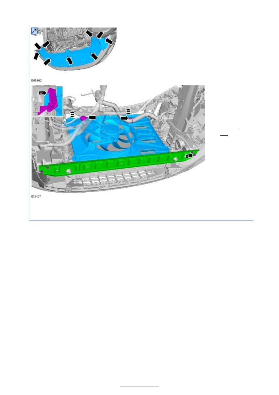
7. Lower the 

radiator and 
condenser 
assembly by 
approximately 
70 mm. 

Torque: 

25 

Nm 

1. To install, reverse the removal procedure. 


Engine Cooling - 2.0L Duratorq-TDCi 
(85kW/115PS) - DW/2.0L Duratorq-TDCi 
(100kW/136PS) - DW/2.0L Duratorq-
TDCi (103kW/140PS) - DW - 
Specifications

S-MAX/Galaxy 2006.5 (02/2006-)


Print


Lubricants, Fluids, Sealers and Adhesives 

Antifreeze 

Cooling System Refill Capacities 

Cooling System Pressure Specification 

Item

Specification

Motorcraft Super Plus Antifreeze

WSS-M97B44–D

Specific Gravity (providing no 

other additive is in coolant)

Approximate percentage of 

Anti-Freeze (by volume)

Remains 

Fluid to

Solidifies 

at

1.061 at +15°C

50%

–25°C (–13°

F)

–37°C (–

35°F)

Description

Liters

Cooling system and heater

8.14

Description

Pressure kpa (psi)

Radiator pressure test

138 (20)

Coolant expansion tank cap release pressure

135 to 155 (19.6 to 22.5)

Engine Cooling - 2.0L Duratorq-TDCi 
(85kW/115PS) - DW/2.0L Duratorq-TDCi 
(100kW/136PS) - DW/2.0L Duratorq-
TDCi (103kW/140PS) - DW - Engine 
Cooling

S-MAX/Galaxy 2006.5 (02/2006-)


Print


Description and Operation 

Coolant circuit 


Description 

Heat exchanger 

Thermostat housing 

Bypass solenoid valve 

Thermostat 

Shutoff solenoid valve 

Radiator 

Oil/coolant heat exchanger 

Coolant reservoir 

Cylinder block 

Coolant pump 

Item

1

2

3

4

5

6

7

8

9

10


Part Number

-

-

-

-

-

-

-

-

-

-

-

EGR cooler 

Thermostat housing 


Description 

Bypass solenoid valve 

Connection to coolant reservoir 

Connection to radiator inlet 

Connection to the oil/coolant heat exchanger 

Connection to radiator outlet 

Connection to coolant pump 

Connection to heat exchanger 

engine coolant temperature (ECT) sensor 

WARNING: The ECT sensor must not be removed while the cooling system is 

pressurised. 

The thermostat housing is attached to the cylinder head on the transmission side of the 
engine. 

The ECT sensor is located on the thermostat housing and is attached by means of a clip. 

The thermostat housing contains the thermostat and the bypass solenoid valve. The 
thermostat is a conventional design. 

The thermostat housing is made of plastic and cannot be disassembled when the vehicle is 
serviced. The ECT sensor can be replaced separately. 

Operating principle 

The shut-off solenoid valve is located in the feed from the thermostat housing to the coolant 
reservoir. It limits coolant flow to the coolant reservoir during the engine warm up phase. 

The bypass solenoid valve is located between the coolant outlet on the cylinder head and 
the supply to the coolant pump. It limits the coolant flow to the coolant pump during the 

11

Item

1

2

3

4

5

6

7

8

-


Part Number

-

-

-

-

-

-

-

-


Content   ..  344  345  346  347   ..