Ford Galaxy / Ford S-MAX. Manual - part 259
 

  Index      Ford     Ford Galaxy / Ford S-MAX - service repair manual 2006 year


Search            


Content   ..  257  258  259  260   ..


Ford Galaxy / Ford S-MAX. Manual - part 259


24.

CAUTION: Contact of the engine upper cover with the cowl panel may cause 

damage (scratches) on the engine upper cover. Failure to follow this instruction 
may cause the engine upper cover to be damaged. 

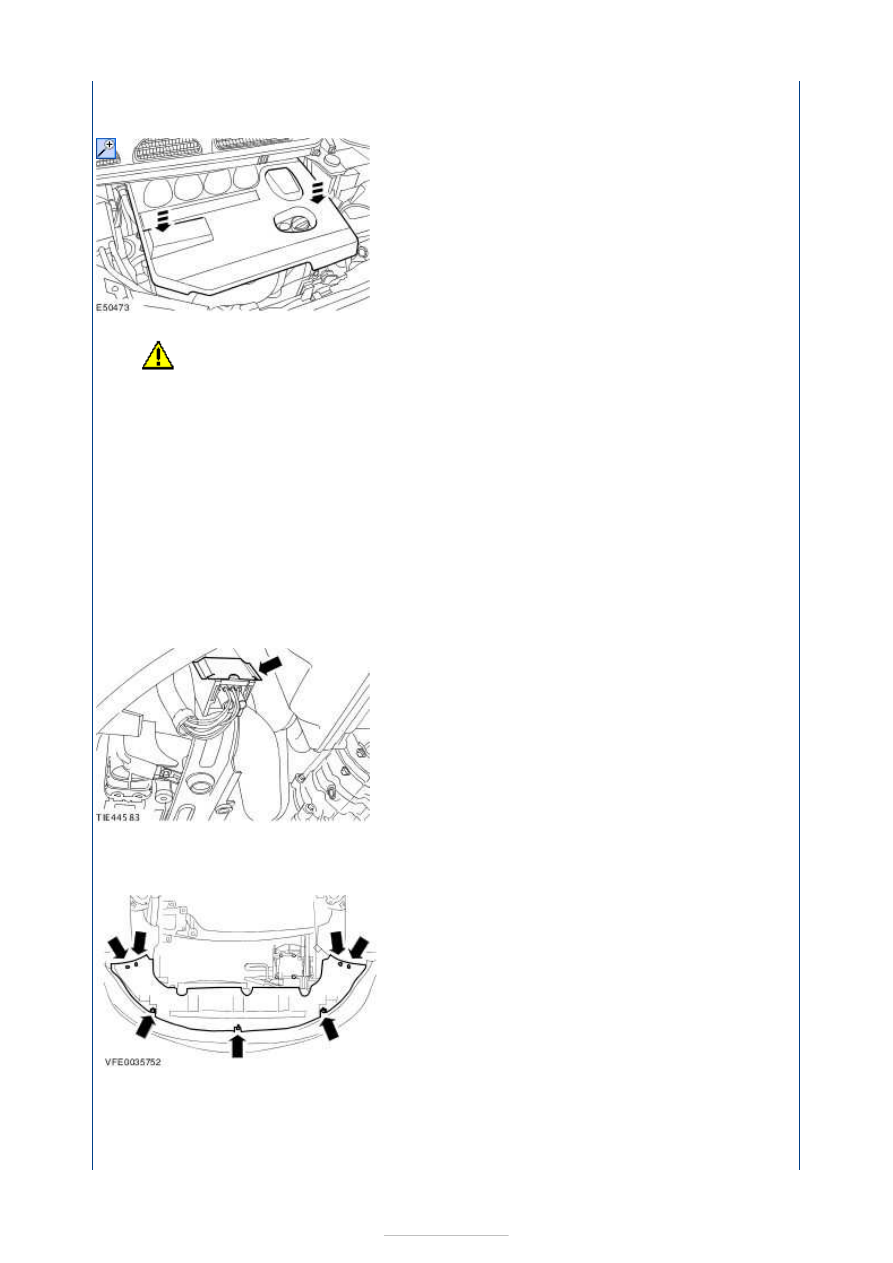
24. Put the engine cover into installation position and clip it in place by pressing at 

the places shown. 

Make sure that the engine upper cover is fully engaged in the area of the fuel filter, 
if necessary apply more pressure in the areas shown. 

25. 25. Install the cowl panel grille.  

REFER to: 

Cowl Panel Grille

 (501-02 Front End Body Panels, Removal and 

Installation). 

26. 26. Raise and support the vehicle. REFER to: 

Lifting

 (100-02 Jacking and Lifting, 

Description and Operation). 

27. 27. Install the glow plug relay. 

28. 28. Install the radiator undershield. 


29. 29. Install the engine undershield. 

30. 30. Lower the vehicle. 

31. 31. Reset the PCM fault memory. 

Measure the oil pressure (21 113 0) 

The oil pressure depends on various factors (engine speed, oil temperature, oil viscosity, 
amount of oil filter contamination etc.). 

Measure the oil pressure 

1. 1. Raise and support the vehicle. REFER to: 

Lifting

 (100-02 Jacking and Lifting, 

Description and Operation). 

2. 2. Remove the engine under shield. 

3. 3. Disconnect the oil pressure switch electrical connector. 


4. 4. Remove the oil pressure switch. 

5. 5. Attach the oil pressure gauge with the oil pressure gauge connector. 

6.

NOTE: Measure the oil pressure at the specified engine speed. Measure the oil 
pressure at an oil temperature of 80° C. 
NOTE: Measure the oil pressure at 2000 rpm and at 4000 rpm. 
NOTE: Oil pressure at 2000 rpm: 2.0 bar. 
NOTE: Oil pressure at 4000 rpm: 4.0 bar. 

6. Check the oil pressure. 

7. 7. Detach the oil pressure gauge and the oil pressure gauge connector. 

8. 8. Coat the oil pressure switch with 

adhesive


9. 9. Install the oil pressure switch. 

10. 10. Connect the oil pressure switch electrical connector. 

11. 11. Install the engine under shield. 

12. 12. Lower the vehicle. 

Valve train analysis - static (engine off) 

Remove the valve cover.  

Check all valve train components for damage and wear. Ensure that only original 
components are installed and that all bolts and nuts have been tightened to the correct 
tightening torque. REFER to: 

Specifications

 (303-01F Engine - 2.0L Duratorq-TDCi 

(85kW/115PS) - DW/2.0L Duratorq-TDCi (100kW/136PS) - DW/2.0L Duratorq-TDCi 
(103kW/140PS) - DW, Emission Requirements: Stage IV, Specifications). 


Content   ..  257  258  259  260   ..