Ford Galaxy / Ford S-MAX. Manual - part 255
 

  Index      Ford     Ford Galaxy / Ford S-MAX - service repair manual 2006 year


Search            


Content   ..  253  254  255  256   ..


Ford Galaxy / Ford S-MAX. Manual - part 255


Description 

Timing belt pulley - exhaust camshaft 

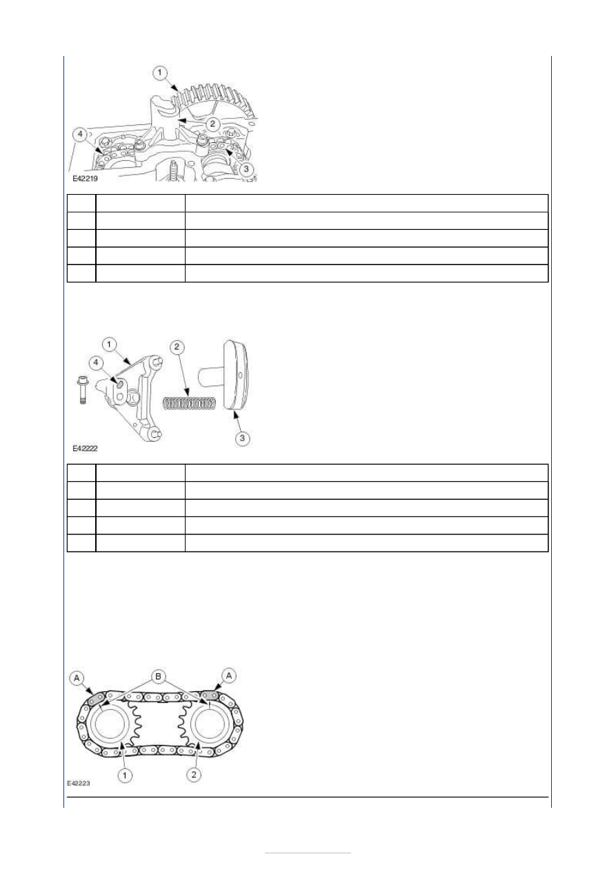
Timing chain tensioner 

Exhaust camshaft sprocket 

Inlet camshaft sprocket 

The timing chain tensioner is attached to the upper part of the cylinder head, between the 
camshaft sprockets. 

Two securing bolts are used to secure the chain tensioner. 


Description 

Timing chain tensioner housing 

Spring 

Timing chain guide 

Oil bore 

The timing chain guide is made of plastic. 

Timing chain guide wear is compensated for by a spring loaded timing chain tensioner. 

Because the timing chain tensioner is connected to the engine oil supply circuit, the 
components are lubricated and chain noise is reliably prevented. 

A second timing chain guide is attached to the cylinder head lower section. 

Timing chain 


Item

1

2

3

4

Item

1

2

3

4


Part Number

-

-

-

-


Part Number

-

-

-

-


Part Number

Description 

Exhaust camshaft 

Inlet camshaft 

Bright chrome-finished chain links 

Markings on the sprockets 

The inlet camshaft is driven via a timing chain. 

The timing chain is tensioned using an automatic chain tensioner. 

The timing chain has two bright chrome-finished chain links (A). When installed, these two 
markings must align with the arrow marks (B) on the sprockets. 

Pistons and piston rings 


Description 

Upper compression ring 

Lower compression ring 

Oil scraper ring 

The light alloy pistons have a combustion chamber incorporated into the centre of the piston 
crown. This optimises swirling of the fuel/air mixture. 

Two recesses are incorporated into each piston crown. 

In order to minimise friction, particularly during the running-in phase, the piston stem has a 
graphite-based coating. 

The piston pin is a floating fit and is held in position by two snap rings. 

Cylinder block 

Item

1

2

(A)

(B)

Item

1

2

3

-

-

-

-


Part Number

-

-

-

NOTE: Refer to the current service literature for the exact procedure and the correct 
measurements for machining. 

The cylinder block is made of cast iron and has no cylinder liners. 

The running surfaces of the cylinders are worked directly into the cylinder block. 

The mating face of the cylinder block with the cylinder head can be re-worked. 

Two holes are provided in the cylinder block, for the guide sleeves used to secure the 
cylinder head gasket. 

Connecting rods 


Description 

Big-end bearing shells 

NOTE: Refer to the current service literature for the exact procedure and the correct 
tightening torques for installing the big end bearings. 

The connecting rods are made of forged steel. 

The big-end bearing caps are cut and machined at the joins to the connecting rod. 

The big end bearing shells have retaining lugs to prevent radial movement. 

The retaining nuts are tightened in three stages. In the third stage the nuts are tightened 
to a specified angle. 

The connecting rods and big-end bearing caps are paired and must not be mixed up. 

Crankshaft main bearings 

Item

1


Part Number

-


Description 

Colour marking 

Marking 

Barcode 

Alphanumerical code 

Thrust washers 

Marking 

For accurate adjustment of the crankshaft bearing clearance, the crankshaft bearing shells 
in the crankshaft main bearing caps are available in five different thicknesses. 

The upper crankshaft main bearings (cylinder block side) are only available in one 
thickness. 

Marks on the cylinder block (1) and on the crankshaft (timing side) (4) indicate the 
thicknesses of the crankshaft bearing shells installed. 

The barcode (2) is for production and the alphanumeric code (3) for service operations. 

Retaining lugs on the crankshaft bearing shells prevent radial movement. 

NOTE: The crankshaft main bearing caps must be installed in the correct position. 
NOTE: Cylinder 1 is located on the transmission side. 

Item

A

1

2

3

4

5


Part Number

-

-

-

-

-

-


Content   ..  253  254  255  256   ..