Ford Galaxy / Ford S-MAX. Manual - part 254
 

  Index      Ford     Ford Galaxy / Ford S-MAX - service repair manual 2006 year


Search            


Content   ..  252  253  254  255   ..


Ford Galaxy / Ford S-MAX. Manual - part 254


The valve cover and the inlet manifold form one assembly and are made of plastic. 

The PCV valve is also located on the valve cover. 

It is sealed off from the cylinder head with a separate seal. 

The cylinder head's intake ports and injector ports are each sealed off from the inlet 
manifold by four sealing rings. 

NOTE: Refer to the current service literature for precise details of how to assemble the 
valve cover and inlet manifold. 

Before re-installing the valve cover and the inlet manifold, carefully check the sealing rings 
for damage and renew if necessary. 

Cylinder head 


Description 

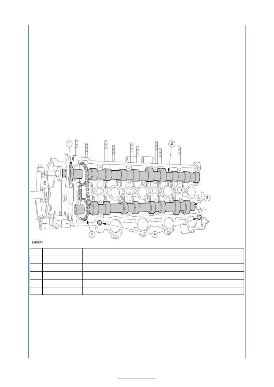
Seal 

Exhaust camshaft 

Inlet camshaft 

Alignment sleeves 

Timing chain 

The aluminium cylinder head has four valves per combustion chamber. The valve seats and 
guides are made of sintered steel. 

The inlet ports are located on the front of the cylinder head, the exhaust ports at the back 
(with respect to the direction of travel). 

Item

1

2

3

4

5


Part Number

-

-

-

-

-


Description 

Inlet ports 

Cylinder head upper part 

Cylinder head lower part 

Oil supply hole 

NOTE: The upper and lower parts of the cylinder head are matched to each other and 
cannot be renewed separately. 
NOTE: It is important to ensure that the oil supply holes are not blocked by sealant when 
the two parts of the cylinder head are brought together. 

The cylinder head is made of two separate parts. This special design ensures that the 
overall structure is stronger. 

The upper and lower parts of the cylinder head are milled in a single operation and are 
accurately positioned with two alignment sleeves. 

The lower part of the cylinder head is bolted to the cylinder block. 

The upper halves of the camshaft mountings are incorporated into the upper part of the 
cylinder head. Here the camshafts run directly in aluminium, without additional bearing 
shells. 

The upper part of the cylinder head features top-entry intake ports. 

The two individual parts are sealed using a one-component, silicone-based sealant when 
they are joined together. 

Valve train 

Item

1

2

3

4


Part Number

-

-

-

-


Description 

Exhaust camshaft 

Inlet camshaft 

Roller cam follower 

Hydraulic tappet 

The inlet valves are made entirely of one material. The heads and stems of the exhaust 
valves are manufactured from different materials and are joined to one another by means 
of friction welding. 

By using roller followers, it has been possible to keep valve actuation friction losses low. 

Valve clearance adjustment is done automatically by the hydraulic tappets. As a result, 
there is no need to adjust the valve clearances. 

The hydraulic tappets are connected with the engine's oil circuit by oil ports cast into the 
cylinder head. 

Camshafts 


Description 

Exhaust camshaft 

Drive - fuel pump 

Item

1

2

3

4

Item

1

2


Part Number

-

-

-

-


Part Number

-

-

-

Drive - vacuum pump 

Inlet camshaft 

The inlet and exhaust camshafts are made from steel tubes. The cams and ends of the 
camshaft are shrunk on. 

Each camshaft runs directly in aluminium in five bearings, without additional bearing shells. 

The vacuum pump is flange-mounted onto the rear of the inlet camshaft and is driven 
directly. 

The fuel pump is flange-mounted onto the rear of the exhaust camshaft and is also driven 
directly. 

Camshaft drive 


Description 

Bore for timing peg 

Idler pulley 

Crankshaft timing pulley 

Coolant pump pulley 

Tensioning pulley 

NOTE: A spacer shim is located between the cylinder block and the idler pulley (2); this 
must be re-fitted when carrying out installation work. 

The exhaust camshaft is driven by a toothed belt. The toothed belt also drives the coolant 
pump. 

The toothed belt drive has an automatic tensioning pulley. The tensioning pulley operates 
by spring force. 

A feather key specifies the installation position of the exhaust camshaft timing pulley and 
the crankshaft timing pulley. 

A hole is located on the exhaust camshaft timing pulley into which can be inserted the 
timing pin (special tool) to adjust the timing. 

Timing chain tensioner 

3

4

Item

1

2

3

4

5

-


Part Number

-

-

-

-

-


Content   ..  252  253  254  255   ..