Ford Galaxy / Ford S-MAX. Manual - part 223
 

  Index      Ford     Ford Galaxy / Ford S-MAX - service repair manual 2006 year


Search            


Content   ..  221  222  223  224   ..


Ford Galaxy / Ford S-MAX. Manual - part 223


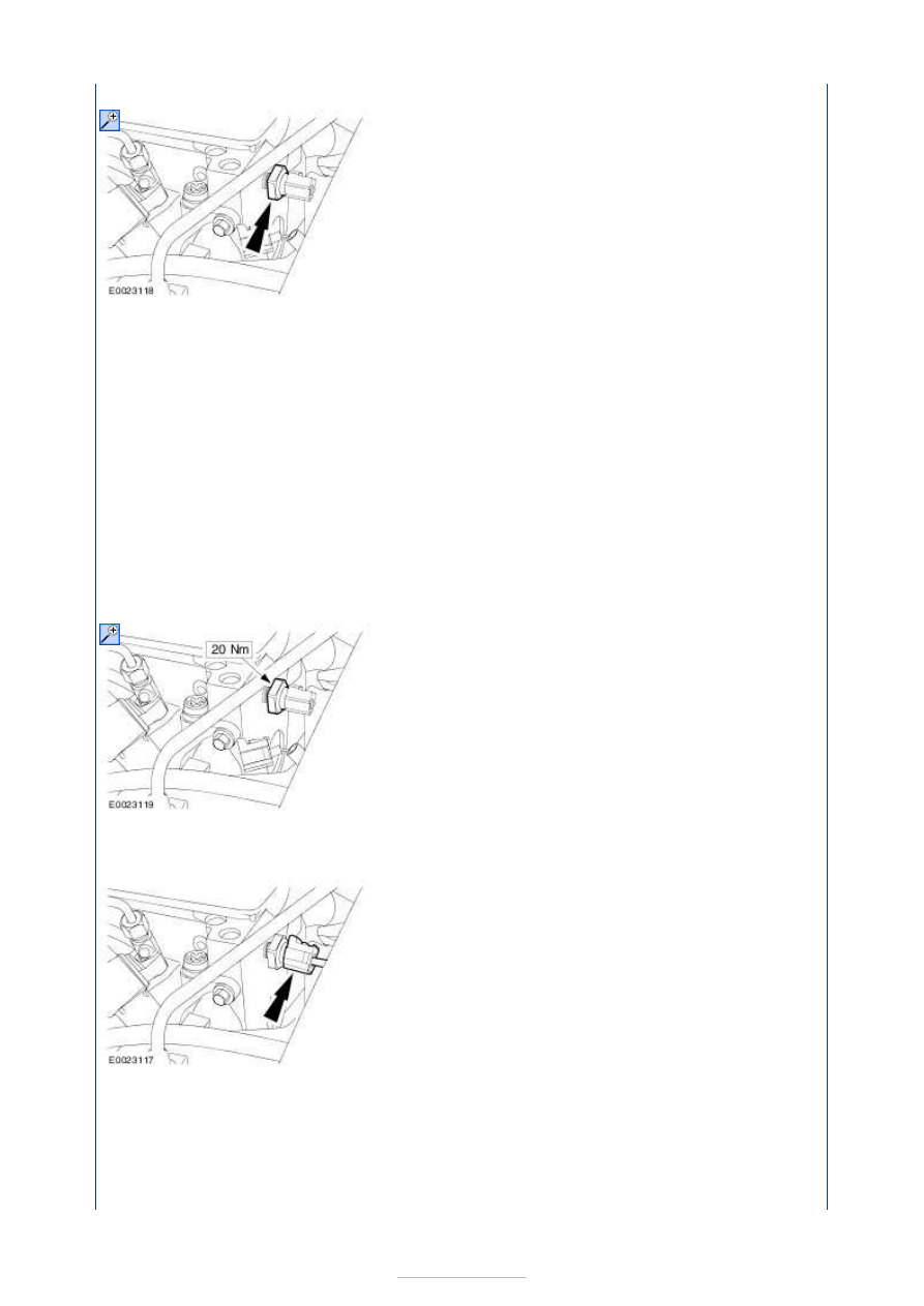
4. 4. Remove the oil pressure switch (components shown removed for clarity). 

5.

NOTE: Measure the oil pressure at the specified engine speed. Measure the oil 
pressure at an oil temperature of 80° C. 
NOTE: Measure the oil pressure at idle speed and at 2000 rpm. 
NOTE: Oil pressure at idle speed: 0.75 bar. 
NOTE: Oil pressure at 2000 rpm: 1.5 bar. 

5. Attach the oil pressure gauge with the oil pressure gauge connector. 

6. 6. Check the oil pressure. 

7. 7. Detach the oil pressure gauge and the oil pressure gauge connector. 

8. 8. Coat the oil pressure switch with 

adhesive

9. 9. Install the oil pressure switch. 

10. 10. Connect the oil pressure switch electrical connector. 

11. 11. Apply soap solution to the ball clip mountings in the engine upper cover.  

Soap solution (maximum concentration of soap in water 1:200).  


12.

CAUTION: Contact of the engine upper cover with the cowl panel may cause 

damage (scratches) on the engine upper cover. Failure to follow this instruction 
may cause the engine upper cover to be damaged.  

12. Put the engine cover into installation position and clip it in place by pressing at 

the places shown.  

Make sure that the engine upper cover is fully engaged in the area of the fuel filter, 
if necessary apply more pressure in the areas shown.  

Valve train analysis - static (engine off) 

Remove the valve cover.  

Check all valve train components for damage and wear. Ensure that only original 
components are installed and that all bolts and nuts have been tightened to the correct 
tightening torque. 


Engine - 1.8L Duratorq-TDCi 
(74kW/100PS) - Lynx/1.8L Duratorq-
TDCi (92kW/125PS) - Lynx - Valve 
Clearance Adjustment

S-MAX/Galaxy 2006.5 (02/2006-)


Print


General Procedures 

Special Tool(s) 

303-195 
Compressor, Valve Spring 

303-196 
Pliers, Valve Shim 

1. Remove the valve cover. 

Refer to: 

Valve Cover

 (303-01E Engine - 1.8L 

Duratorq-TDCi (74kW/100PS) - Lynx/1.8L 
Duratorq-TDCi (92kW/125PS) - Lynx, Removal 
and Installation). 

2.  

3. Torque: 20 Nm 

4.

NOTE: Using a suitable feeler gauge, 
measure the valave clearance. 

Rotate the crankshaft until the cam pair of 
the cylinder to be adjusted are pointing 
upwards. 
Check the valve clearance and note the 
values. 
If the values of one or more adjustment 
shims are outside the tolerance range, 
renew the adjustment shim as described in 
the following step. 

5.

NOTE: Rotate the crankshaft by a further 90 
degrees. 
NOTE: The piston of the cylinder to be 
adjusted must not be at TDC. 

Note the thickness of the adjustment shim, 


marked on the underside of the shim. 
Install the new adjustment shim to obtain 
the correct valve clearance. 

Special Tool(s): 

303-195

303-196


6. To install, reverse the removal procedure. 


Content   ..  221  222  223  224   ..