Ford Galaxy / Ford S-MAX. Manual - part 103
 

  Index      Ford     Ford Galaxy / Ford S-MAX - service repair manual 2006 year


Search            


Content   ..  101  102  103  104   ..


Ford Galaxy / Ford S-MAX. Manual - part 103


Check the ignition switch electrical connector. 

Is the ignition switch electrical connector clean and 
secure? 
Yes 

GO to A2

.  

No 

CLEAN and SECURE the ignition switch electrical 
connector. TEST the system for normal operation. 

A2: CHECK FOR VOLTAGE ON CIRCUIT SBP24A (VT/RD)

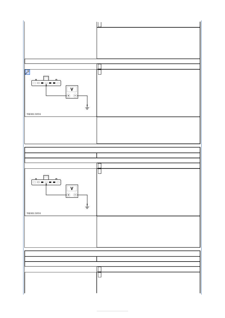
Disconnect Ignition Switch C2DC32. 

Measure the voltage between the ignition switch 
C2DC32 Pin 4, circuit SBP24A (VT/RD), harness 

side and ground. 

Is the voltage greater than 10 volts? 
Yes 

VERIFY the customers concern. 

No 

REPAIR the circuit SBP24A (VT/RD). TEST the 
system for normal operation. 

PINPOINT TEST B : NO POWER IN ACC 

TEST CONDITIONS

DETAILS/RESULTS/ACTIONS

B1: CHECK FOR VOLTAGE ON CIRCUIT SBP24A (VT/RD)

Disconnect Ignition Switch C2DC32. 

Measure the voltage between the ignition switch 
C2DC32 Pin 4, circuit SBP24A (VT/RD), harness 

side and ground. 

Is the voltage greater than 10 volts? 
Yes 

REPAIR circuit CDC33A (VT/GN). TEST the system 
for normal operation. 

No 

REPAIR circuit SBP24A (VT/RD). TEST the system 
for normal operation. 

PINPOINT TEST C : NO POWER IN RUN 

TEST CONDITIONS

DETAILS/RESULTS/ACTIONS

C1: CHECK FOR VOLTAGE ON CIRCUIT SBP24A (VT/RD)

Disconnect Ignition Switch C2DC32. 

Measure the voltage between the ignition switch 
CDC32 Pin 4, circuit CDC33A (VT/GN), harness side 

and ground. 


Is the voltage greater than 10 volts? 
Yes 

REPAIR the circuit CDC32D (BN/YE). TEST the 
system for normal operation. 

No 

REPAIR the circuit SBP24A (VT/RD). TEST the 
system for normal operation. 

PINPOINT TEST D : NO POWER IN START 

TEST CONDITIONS

DETAILS/RESULTS/ACTIONS

D1: CHECK FOR VOLTAGE ON CIRCUIT SBP24A (VT/RD)

Disconnect Ignition Switch CDC32. 

Measure the voltage between the ignition switch 
CDC32 Pin 4, circuit SBP77B (RD/GY) harness side 

and ground. 

Is the voltage greater than 10 volts? 
Yes 

REPAIR circuit CDC35F (BU/WH). TEST the system 
for normal operation. 

No 

REPAIR circuit SBP24A (VT/RD). TEST the system 
for normal operation. 


Steering Column Switches - Steering 
Column Multifunction Switch LH

S-MAX/Galaxy 2006.5 (02/2006-)


Print


Removal and Installation 

Removal 

NOTE: Removal steps in this procedure may contain installation details. 

Installation 

1. Disconnect the battery ground cable.  

Refer to: 

Battery Disconnect and Connect

 (414-

01 Battery, Mounting and Cables, General 
Procedures). 

2.  

3.  

4.  

1. To install, reverse the removal procedure. 


Steering Column Switches - Steering 
Column Multifunction Switch RH

S-MAX/Galaxy 2006.5 (02/2006-)


Print


Removal and Installation 

Removal 

NOTE: Removal steps in this procedure may contain installation details. 

Installation 

1. Disconnect the battery ground cable.  

Refer to: 

Battery Disconnect and Connect

 (414-

01 Battery, Mounting and Cables, General 
Procedures). 

2.  

3.  

4.  

1. To install, reverse the removal procedure. 


Content   ..  101  102  103  104   ..