Ford Galaxy / Ford S-MAX. Manual - part 102
 

  Index      Ford     Ford Galaxy / Ford S-MAX - service repair manual 2006 year


Search            


Content   ..  100  101  102  103   ..


Ford Galaxy / Ford S-MAX. Manual - part 102


Steering Column - Steering Column

S-MAX/Galaxy 2006.5 (02/2006-)


Print


Disassembly and Assembly 

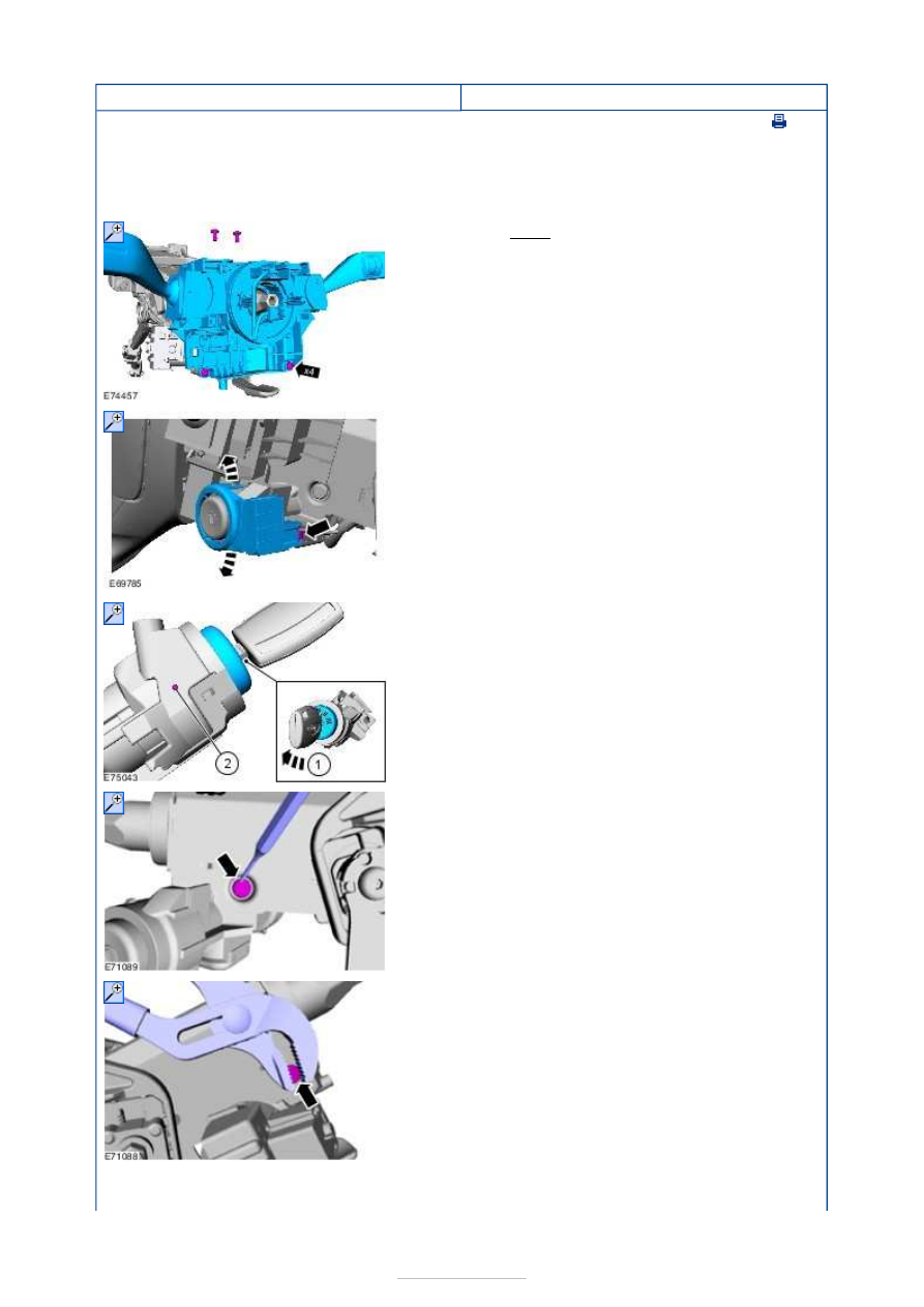
Disassembly 

NOTE: Removal steps in this procedure may contain installation details. 

1. Torque: 3 Nm 

2.  

3.  

4. On both sides. 

5. On both sides. 

6.  


Assembly 

7. To assemble, reverse the disassembly procedure. 


Steering Column Switches - Steering 
Column Switches

S-MAX/Galaxy 2006.5 (02/2006-)


Print


Description and Operation 


Description 

Passive anti-theft system (PATS) transceiver  

Steering column multifunction switch right-hand 

Steering column switch carrier 

Clockspring and steering wheel rotation sensor 

Steering column multifunction switch left-hand 

Ignition switch 

Item

1

2

3

4

5

6


Part Number

-

-

-

-

-

-

Steering Column Switches - Steering 
Column Switches

S-MAX/Galaxy 2006.5 (02/2006-)


Print


Diagnosis and Testing 

Inspection and Verification 

1. 1. Verify the customer concern. 

2. 2. Visually inspect for obvious signs of mechanical or electrical damage. 

Visual Inspection Chart 

3. 3. If an obvious cause for an observed or reported concern is found, correct the cause 

(if possible) before proceeding to the next step. 

4. 4. If the cause is not visually evident, verify the symptom and refer to the Sympton 

Chart. 

Symptom Chart 

Pinpoint Test 

NOTE: Use a digital multimeter for all electrical measurements. 

Electrical

Fuse(s).  
Wiring harness.  
Electrical connector(s).  
Switch(es).  
Battery. 

Symptom

Possible 

Sources

Action

The ignition switch is 
inoperative

Ignition 

switch. 

*

CARRY OUT the Ignition Switch Component Test. 

REFER to the Wiring Diagrams. 

*

Circuit(s). 

*

GO to Pinpoint Test 

A. 


*

No power in ACC

Ignition 

switch. 

*

CARRY OUT the Ignition Switch Component Test. 

REFER to the Wiring Diagrams. 

*

Circuit(s). 

*

GO to Pinpoint Test 

B. 


*

No power in RUN

Ignition 

switch. 

*

CARRY OUT the Ignition Switch Component Test. 

REFER to the Wiring Diagrams. 

*

Circuit(s). 

*

GO to Pinpoint Test 

C. 


*

No power in START

Ignition 

switch. 

*

CARRY OUT the Ignition Switch Component Test. 

REFER to the Wiring Diagrams 

*

Circuit(s). 

*

GO to Pinpoint Test 

D. 


*

The multifunction switch 
does not operate correctly

Switch

(es). 

Circuit(s). 

*

*

REFER to: 

Turn Signal, Cornering and Hazard Lamps


(417-01 Exterior Lighting, Diagnosis and 
Testing), 

Headlamps

 (417-01 Exterior Lighting, 

Diagnosis and Testing), 

Wipers and Washers

 (501-16 Wipers and 

Washers, Diagnosis and Testing). 

*

PINPOINT TEST A : THE IGNITION SWITCH IS INOPERATIVE 

TEST CONDITIONS

DETAILS/RESULTS/ACTIONS

A1: CHECK THE IGNITION SWITCH ELECTRICAL CONNECTOR

Remove the steering column shrouds. 


Content   ..  100  101  102  103   ..