Ford Galaxy / Ford S-MAX. Manual - part 100
 

  Index      Ford     Ford Galaxy / Ford S-MAX - service repair manual 2006 year


Search            


Content   ..  98  99  100  101   ..


Ford Galaxy / Ford S-MAX. Manual - part 100


Steering Column - Steering Column

S-MAX/Galaxy 2006.5 (02/2006-)


Print


Description and Operation 


Description 

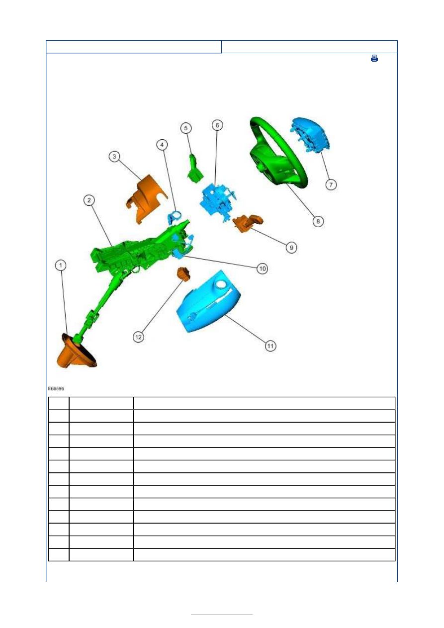
Steering gear to bulkhead seal 

Steering column 

Steering column upper shroud 

Passive anti-theft system (PATS) transceiver 

Windshield wiper/washer switch 

Clockspring and steering wheel rotation sensor assembly 

Driver air bag module 

Steering wheel 

Turn signal lamp switch 

Wiring harness 

Steering column lower shroud 

Ignition switch 

On vehicles with automatic transmission, the steering wheel can be equipped with select 
and shift switches which are integrated into the steering wheel spokes. 

Item

1

2

3

4

5

6

7

8

9

10

11

12


Part Number

-

-

-

-

-

-

-

-

-

-

-

-

If a select and shift switch becomes inoperative, a new steering wheel must be installed. 


Steering Column - Steering Column

S-MAX/Galaxy 2006.5 (02/2006-)


Print


Diagnosis and Testing 

REFER to: 

Steering System

 (211-00 Steering System - General Information, Diagnosis and 

Testing). 

Steering Column - Steering Wheel

S-MAX/Galaxy 2006.5 (02/2006-)


Print


Removal and Installation 

Removal 

NOTE: Removal steps in this procedure may contain installation details. 

Installation 

1. Refer to: 

Driver Air Bag Module - Vehicles Built 

From: 13-07-2009

 (501-20B Supplemental 

Restraint System, Removal and Installation). 
Refer to: 

Driver Air Bag Module - Vehicles Built 

Up To: 13-07-2009

 (501-20B Supplemental 

Restraint System, Removal and Installation). 

2.

CAUTION: Make sure that the steering 

wheel lock is engaged. 
NOTE: Make sure that the road wheels are in 
the straight ahead position. 

3.   

2. Torque: 48 Nm 

4.  

5.

CAUTION: Make sure that the 

clockspring rotor does not rotate. 

Secure the clockspring rotor with adhesive tape 
to the clockspring outer. 

1.

CAUTION: Make sure that the 

clockspring pins are not bent or damaged. 

Carry out the clockspring adjustment procedure, 
if the yellow roller is not visible in the clockspring 


Content   ..  98  99  100  101   ..