Ford Galaxy / Ford S-MAX. Manual - part 1007


  Index      Ford     Ford Galaxy / Ford S-MAX - service repair manual 2006 year


Search            


Content   ..  1005  1006  1007  1008   ..


Ford Galaxy / Ford S-MAX. Manual - part 1007
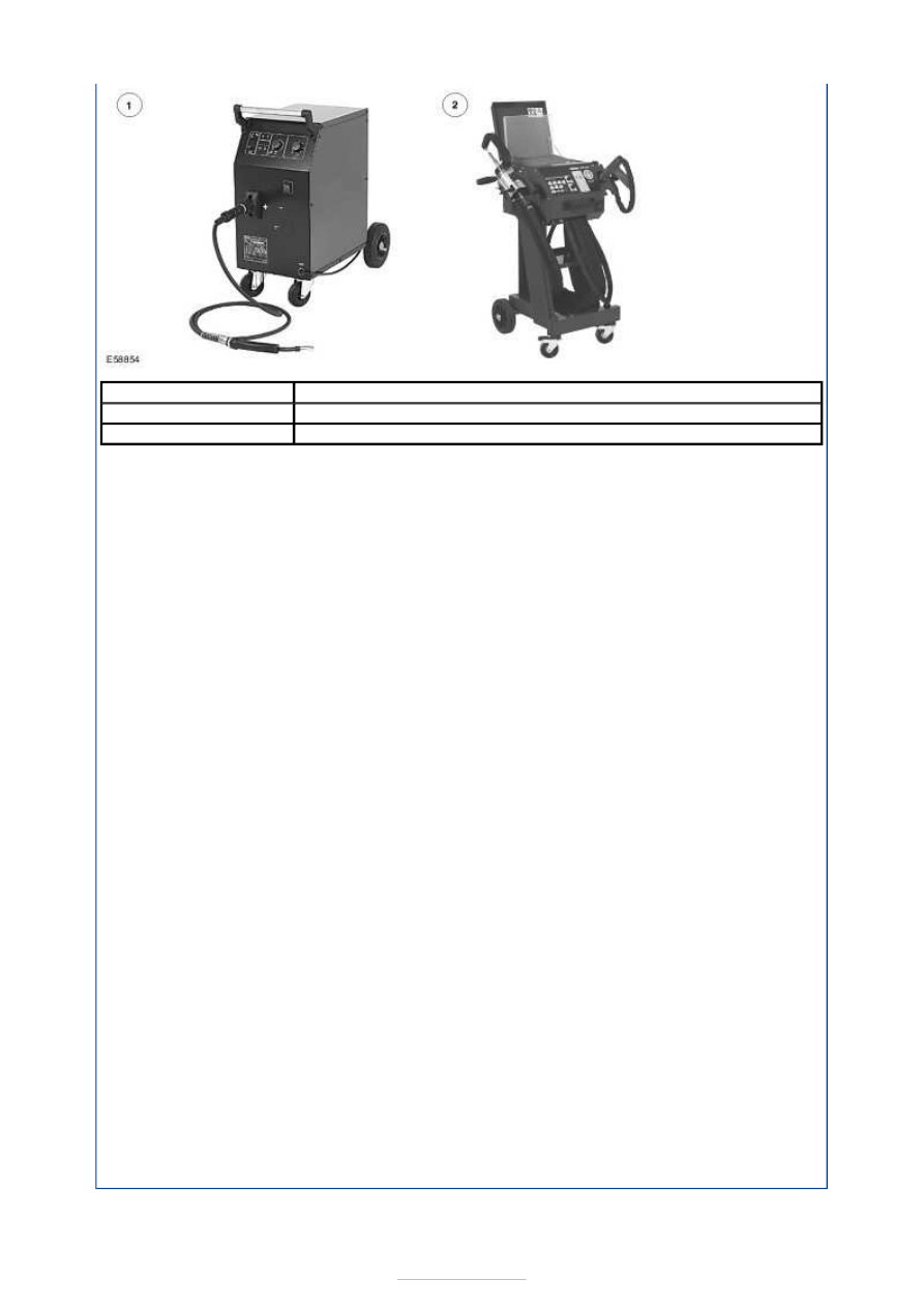


NOTE: If a suitably powerful welding machine is not available and multi-layer panel joints 
with a total thickness of over 3 mm need to be made, puddle welding must be used. 

Although in principle, high and super high-strength panels are adequately or well suited to 
resistance spot welding, considerable problems may arise because of low welding power, 
especially where thicker panels or three layers of panel must be welded together in the 
workshop. In particular, older welding equipment does not have the latest welding 
technology nor welding power and therefore cannot reliably join panel thicknesses greater 
than 3 mm.  

Equipment with inverter technology allows better spot weld quality because of a constant 
high welding current. In addition the high welding current makes shorter welding times 
possible and the electrodes therefore have a longer working life. Inverter welding is a 
further development of electrode welding. 

Further advantages of the new inverter welding equipment are: 

good welding performance with constant quality, even with high switch-on times  
recognition of and compensation for disruptive factors: e.g. primer, adhesive, rust-
prevention paint  
own and pre-set welding programs which can be saved and called up  
quality confirmation through logging of all important welding data  
fast changing of spot welding clamps or spot welding guns as required 

The following functions can be controlled and monitored by programming the welding 
equipment: 

Control of the start conditions by resistance measurement (dirt, paint, bodywork 
adhesive, shunt circuit through the next spot weld).  
Ensuring the optimum welded connection.  
Checking the energy balance, resistance and quality. 

In the case of resistance spot welded connections, faults in the weld are difficult to see 
from the outside. It is therefore absolutely vital to know the particular properties of the 
welding machine being used. A test weld with subsequent peeling test will provide 
information on the quality of the weld. The spot weld itself must not separate, it must tear 
away leaving a hole. 

In the production of vehicle bodies, MIG welding plays a minor role as a joining technique. 
It is used for components subject to high demands, such as threaded plates for axle 
mountings, or at locations which cannot be spot welded for access reasons.  

Description

Description

1

MIG welding machine

2

Resistance spot welding machine


Body Repairs - General Information - 
Establish Repair Method

S-MAX/Galaxy 2006.5 (02/2006-)


Print


Description and Operation 

General 

Before starting accident repair work, make sure that the necessary spare parts and repair 
material are available.  

Planning 

NOTE: The body interconnection is to be maintained if possible. Repair is preferred to 
renewal of body components. Furthermore, check if it is possible to perform a partial 
repair.  

During planning the following job steps must be observed and adhered to:  

Determine the repair method taking into account the information made available in ETIS.  
Work out which repair components will be needed and obtain them.  
Establish what disassembly work is needed.  
Check for specific features such as airbags, route of water drain hoses, electric cables 
and the location of NVH elements.  
Cut out the old parts (only when the new parts are waiting ready).  
Prepare the joint locations.  
Attach the new parts.  
Prepare the area of the repair for painting (grinding welded beads).  
Perform any solder work which is required at the repair location. 

Chronological sequence of repair 

NOTE: Refer to each vehicle specific chapter in the workshop literature for details on the 
individual points. 

The actual sequence of repair can be divided into the following steps: 

Job steps for the coachbuilder: 

Straightening  
Establish separating cuts and mark them. 

Take into account the requirements given in the repair instructions.  
Place the new part ready for use and include it in the repair plan. 

Separate and remove the old part. 

Take into account the special features particular to the vehicle. 

Prepare the joint locations. 

- Sand and align the weld flanges. 
Apply corrosion protection measures. 
Offer up the new part. 

Attach the new component.  
Rework the welded joints (grind welded seams). 

-
-

-

-
-
-

Body Repairs - General Information - 
Alignment Check

S-MAX/Galaxy 2006.5 (02/2006-)


Print


Description and Operation 

General 

If there is concern that the body has been deformed, the body must be measured. Several 
measuring procedures and tools can be used for this purpose. 

With simple measuring systems, it is possible in most cases to draw a conclusion about the 
extent of the damage through a quick measurement without time-consuming assembly 
work (straightening jig). 

NOTE: For the floor pan and the exterior of the vehicle, measuring data is contained in 
the vehicle-specific repair instructions for each vehicle. Manufacturers of measuring and 
straightening jigs create data sheets for this purpose for each vehicle. 

Data sheets with the body frame dimensions for body measurement are specified in the 
model-specific repair instructions in each case. Pay attention to the position of the 
measuring probes for each of the measurements given. A tolerance of ± 3 mm applies to all 
specified dimensions. 

Measuring points that are specified in a curve are to be measured so that the greatest 
distance from the opposite measuring point is reflected. For exact determination of the 
measuring points, enlarged sections are shown. 

Example of measuring the vehicle superstructure 

Example of measuring the floor pan 


Content   ..  1005  1006  1007  1008   ..