Ford Galaxy / Ford S-MAX. Manual - part 67
 

  Index      Ford     Ford Galaxy / Ford S-MAX - service repair manual 2006 year


Search            


Content   ..  65  66  67  68   ..


Ford Galaxy / Ford S-MAX. Manual - part 67


Parking Brake and Actuation - Parking 
Brake

S-MAX/Galaxy 2006.5 (02/2006-)


Print


Description and Operation 

Manual parking brake 

A conventional parking brake system is used with a twin A-frame parking brake control 
lever which is located in the floor console. 

Only the parking brake control is visible, the parking brake control lever is hidden by the 
floor console. 

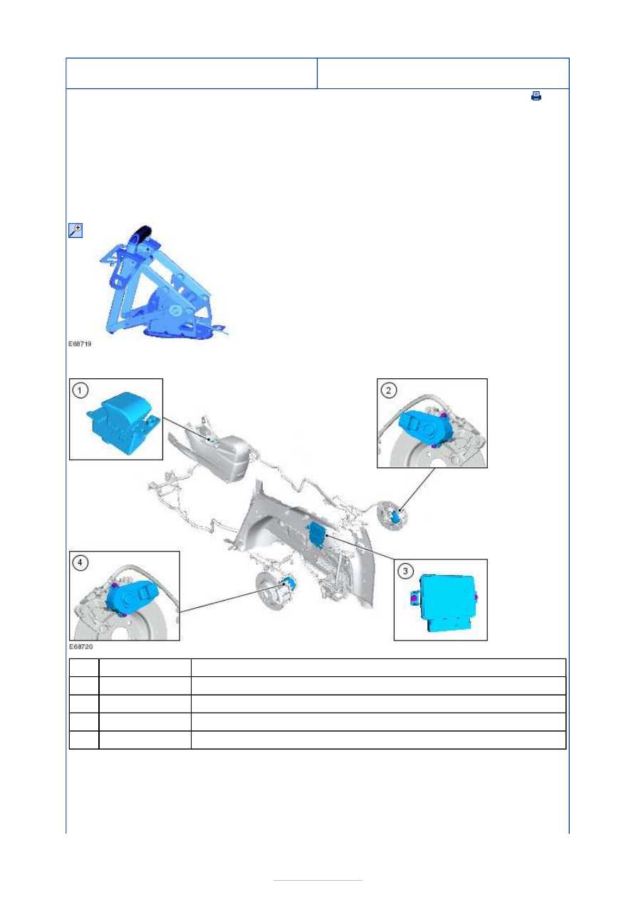
Electronic parking brake (EPB) 


Description 

EPB switch 

Right-hand rear EPB actuator 

EPB module 

Left-hand rear EPB actuator 

An EPB is available as an option for the vehicle. In comparison to a conventional parking 
brake, the EPB offers the following advantages: 

* Ease of operation, due to low operating forces. This is achieved by the use of an electrical 
switch instead of a lever and the parking brake cables are replaced by electrical cables. 

* The EPB is always applied firmly, giving maximum parking brake power in all operating 

Item

1

2

3

4


Part Number

-

-

-

-

conditions. 

* Safety, the vehicle can be slowed down with the EPB if the hydraulics of the brake system 
fail while driving. The system is automatically coordinated with the ABS system to prevent 
the braked wheels from locking. 

The system comprises the following components: 

* EPB module: This is located in the rear stowage area, behind the left-hand rear quarter 
trim panel. The module is the system control unit and operates the rear brake calipers as 
required using information from the EPB switch, the ignition key and various system data 
from the high-speed CAN Bus. 

* EPB Switch: This is a push-pull type switch and is located in the floor console. To release 
the EPB, push the EPB switch down. To engage the EPB, pull the EPB switch up. 

* EPB Actuators: These are attached to the left and right-hand rear brake caliper housings. 
They use an electric motor to operate the calipers by turning a threaded spindle within a 
pressure nut that presses against the brake caliper piston. 

Modes of Operation: 

Static Mode (vehicle stationary): Full application and release of the rear brakes is possible. 
The parking brake will only release if the brake pedal or clutch pedal is depressed at the 
same time as releasing the EPB switch, or when the vehicle is driven away. 

Key Out Apply: The parking brake is automatically applied (auto clamp) when the ignition 
key is removed from the ignition switch. 

Dynamic Mode (vehicle in motion): The parking brake is gradually activated when the EPB 
switch is applied and released when the EPB switch is released. 

Drive Away Assist: This system enables the driver to drive away on an incline without the 
vehicle rolling back unintentionally. After stopping the vehicle on an incline or a descent 
and the parking brake is applied, it will be released when operating the accelerator pedal 
without any further driver intervention. 

Disc Temperature Mode: If after bringing the vehicle to a halt the rear brake discs 
temperature exceeds 300°C, the parking brake will be activated and will not release until 
the brake discs have sufficiently cooled. 

Stall Apply: If the engine is stalled the parking brake is automatically applied. 

Service mode activation and deactivation 

On vehicles with Electronic Parking Brake (EPB) it is required to activate the service mode 
before any work is started. Also the deactivation of the service mode is required after the 
repair. The Service mode can be activated either using the vehicle system or using the Ford 
diagnostic system. For additional information, refer to 206-05 Parking Brake and Actuation, 
General Procedures. 

A separate procedure is available if the vehicle is without power. For additional information, 
refer to 206-05 Parking Brake and Actuation, General Procedures. 

Parking Brake and Actuation - Parking 
Brake

S-MAX/Galaxy 2006.5 (02/2006-)


Print


Diagnosis and Testing 

Refer to Wiring Diagrams Section 206-05, for schematic and connector 
information.  

General Equipment 

Principles of Operation 

Inspection and Verification 

1. 1. Verify the customer concern. 

2. 2. Visually inspect for obvious signs of mechanical or electrical damage. 

Visual Inspection Chart 

3. 3. If an obvious cause for an observed or reported concern is found, correct the cause 

(if possible) before proceeding to the next step 

4. 4. If the cause is not visually evident, verify the symptom and refer to the Symptom 

Chart. 

Symptom Chart 

Worldwide Diagnostic System (WDS)

Mechanical

Electrical

Parking brake switch  

Clutch pedal switch  

Caliper  

Brake disc  

Brake pad 

Parking brake switch  

Clutch pedal switch  

Fuse(s)  

Electrical connector(s)  

Circuit(s) 

Symptom

Possible Sources

Action

Poor drive away release

Reversing lamp 

switch stuck on. 

*

Check the operation of the reversing 

lamps.  
REFER to: 

Reversing Lamps

 (417-01 

Exterior Lighting, Diagnosis and 
Testing). 

*

Clutch changed 

and not re-learned. 

*

Carry out several drive aways with 

manual operation of the EPB switch. 

*

Drive away release not 
possible

Clutch pedal 

position switch not 
depressed fully. 

*

Check the correct clutch pedal 

position switch is fitted. Advise the 
customer that the clutch must be fully 
depressed to activate drive away 
release. 

*

Accelerator pedal 

not depressed 
sufficiently. 

*

Advise the customer that the 

accelerator pedal must be depressed 
at least 10% to activate drive away 
release. 

*

Drive away release 

option configured 
out. 

*

Connect WDS and check the 

configuration.  
REFER to: 

Module Configuration

 (418-

01 Module Configuration, General 
Procedures). 

*

Automatic 'key out' EPB 
activation not possible

Automatic 'key out' 

EPB activation 

*

Connect WDS and check the 

configuration.  

*

option configured 
out. 

REFER to: 

Module Configuration

 (418-

01 Module Configuration, General 
Procedures). 

DTC C2005.09: Right actuator 
fault

Parking brake 

release actuator.  

*

GO to Pinpoint Test 

A. 


*

DTC C2005.71: Right actuator 
fault

Parking brake 

release actuator.  

*

GO to Pinpoint Test 

A. 


*

DTC C2005.77: Right actuator 
fault

Battery. 
Charging system. 
Parking brake 

release actuator.  

Circuit(s). 

*
*
*

*

GO to Pinpoint Test 

B. 


*

DTC C2005.95: Right actuator 
fault

Parking brake 

release actuator. 

*

REPEAT the self-test, CLEAR the 

DTCs. Apply and release the parking 
brake. If the DTC remains, GO to 
Pinpoint Test 

C. 


*

DTC C2006.09: Left actuator 
fault

Parking brake 

release actuator. 

*

GO to Pinpoint Test 

D. 


*

DTC C2006.71: Left actuator 
fault

Parking brake 

release actuator. 

*

GO to Pinpoint Test 

D. 


*

DTC C2006.77: Left actuator 
fault

Battery. 
Charging system. 
Parking brake 

release actuator. 

Circuit(s). 

*
*
*

*

GO to Pinpoint Test 

E. 


*

DTC C2006.95: Left actuator 
fault

Parking brake 

release actuator. 

*

REPEAT the self-test, CLEAR the 

DTCs. Apply and release the parking 
brake. If the DTC remains, GO to 
Pinpoint Test 

F. 


*

DTC C2007.01: Right motor 
fault

Parking brake 

release actuator. 

Circuit(s). 

*

*

GO to Pinpoint Test 

G. 


*

DTC C2007.11: Right motor 
fault

Parking brake 

release actuator. 

Circuit(s). 

*

*

GO to Pinpoint Test 

H. 


*

DTC C2007.12: Right motor 
fault

Parking brake 

release actuator. 

Circuit(s). 

*

*

GO to Pinpoint Test 

I. 


*

DTC C2007.13: Right motor 
fault

Parking brake 

release actuator. 

Circuit(s). 

*

*

GO to Pinpoint Test 

J. 


*

DTC C2007.16: Right motor 
fault

Parking brake 

release actuator. 

Circuit(s). 

*

*

GO to Pinpoint Test 

K. 


*

DTC C2007.17: Right motor 
fault

Parking brake 

release actuator. 

Circuit(s). 

*

*

GO to Pinpoint Test 

L. 


*

DTC C2007.18: Right motor 
fault

Parking brake 

release actuator. 

Circuit(s). 

*

*

GO to Pinpoint Test 

G. 


*

DTC C2007.19: Right motor 
fault

Parking brake 

release actuator. 

Circuit(s). 

*

*

GO to Pinpoint Test 

M. 


*

DTC C2007.1D: Right motor 
fault

Parking brake 

release actuator. 

*

GO to Pinpoint Test 

N. 


*

DTC C2008.01: Left motor 
fault

Parking brake 

release actuator. 

Circuit(s). 

*

*

GO to Pinpoint Test 

O. 


*


Content   ..  65  66  67  68   ..