Ford Galaxy / Ford S-MAX. Manual - part 29
 

  Index      Ford     Ford Galaxy / Ford S-MAX - service repair manual 2006 year


Search            


Content   ..  27  28  29  30   ..


Ford Galaxy / Ford S-MAX. Manual - part 29


PINPOINT TEST P : SWITCH ILLUMINATION CIRCUIT - SHORT TO GROUND 

TEST CONDITIONS

DETAILS/RESULTS/ACTIONS

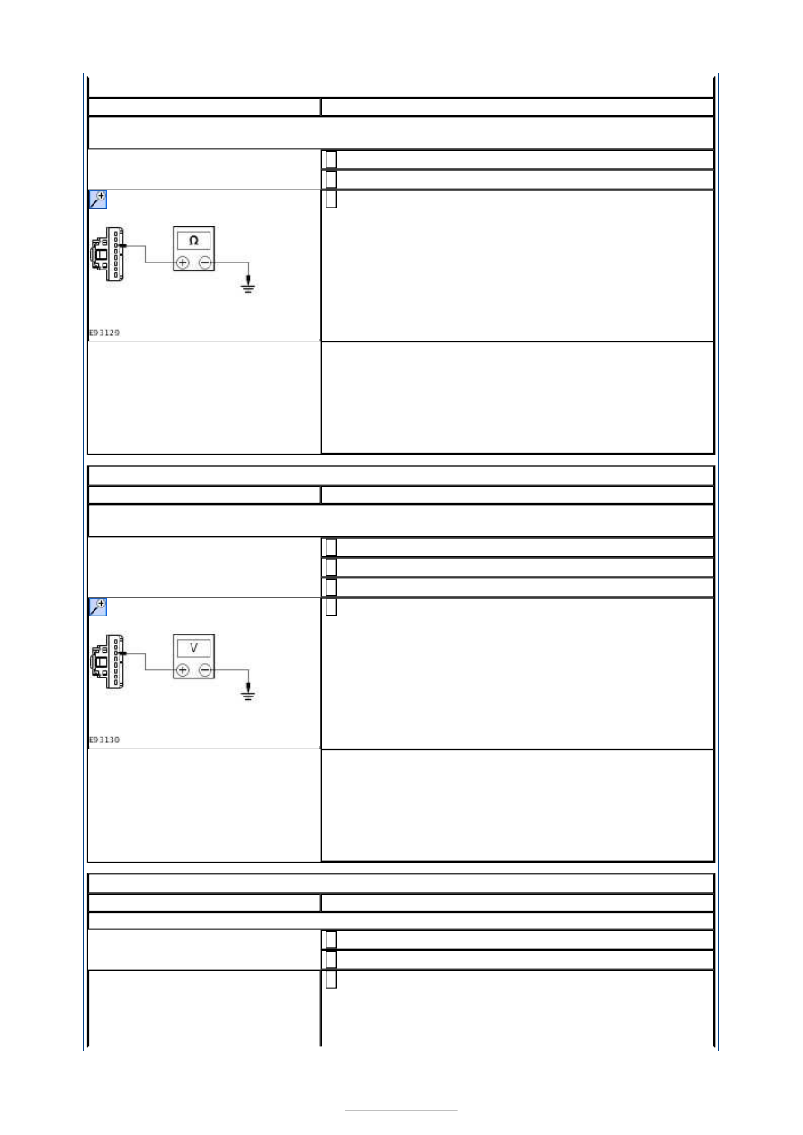
P1: CHECK CIRCUITS CCD15A (WH/OG) AND CCD15B (WH/OG) FOR SHORT TO 
GROUND

Disconnect Adaptive Damping Module C4CD01-B. 

Disconnect Adaptive Damping Control Switch C2CD14. 

Measure the resistance between the adaptive damping 
control switch C2CD14 pin 3, circuit CCD15A (WH/OG), 

harness side and ground. 

Is the resistance greater than 10,000 ohms (open circuit)? 
Yes 

INSTALL a new adaptive damping control switch. TEST 
the system for normal operation. 

No 

REPAIR the circuit. TEST the system for normal 
operation. 

PINPOINT TEST Q : SWITCH ILLUMINATION CIRCUIT - SHORT TO POWER 

TEST CONDITIONS

DETAILS/RESULTS/ACTIONS

Q1: CHECK CIRCUITS CCD15A (WH/OG) AND CCD15B (WH/OG) FOR SHORT TO 
POWER

Disconnect Adaptive Damping Module C4CD01-B. 

Disconnect Adaptive Damping Control Switch C2CD14. 

Ignition switch in position II. 

Measure the voltage between the adaptive damping 
control switch C2CD14 pin 3, circuit CCD15A (WH/OG), 

harness side and ground. 

Is the voltage 0 volts? 
Yes 

INSTALL a new adaptive damping control switch. TEST 
the system for normal operation. 

No 

REPAIR the circuit. TEST the system for normal 
operation. 

PINPOINT TEST R : SWITCH ILLUMINATION CIRCUIT - OPEN CIRCUIT 

TEST CONDITIONS

DETAILS/RESULTS/ACTIONS

R1: CHECK CIRCUITS CCD15A (WH/OG) AND CCD15B (WH/OG) FOR OPEN CIRCUIT

Disconnect Adaptive Damping Module C4CD01-B. 

Disconnect Adaptive Damping Control Switch C2CD14. 

Measure the resistance between the adaptive damping 
control switch C2CD14 pin 3, circuit CCD15A (WH/OG), 

harness side and the adaptive damping module 
C4CD01-B pin 3, circuit CCD15B (WH/OG), harness 


side. 

Is the resistance less than 1 ohm? 
Yes 

GO to R2

.  

No 

REPAIR the circuit. TEST the system for normal 
operation. 

R2: CHECK CIRCUITS RCD21A (VT/OG) AND RCD21B (VT/OG) FOR OPEN CIRCUIT

Measure the resistance between the adaptive damping 
control switch C2CD14 pin 1, circuit RCD21A (VT/OG), 

harness side and the adaptive damping module 
C4CD01-B pin 21, circuit RDC21B (VT/OG), harness 
side. 

Is the resistance less than 1 ohm? 
Yes 

INSTALL a new adaptive damping control switch. TEST 
the system for normal operation. 

No 

REPAIR the circuit. TEST the system for normal 
operation. 

PINPOINT TEST S : SWITCH CIRCUIT - SHORT TO GROUND 

TEST CONDITIONS

DETAILS/RESULTS/ACTIONS

S1: CHECK CIRCUITS CCD22A (BN/BU) AND CCD22B (BN/BU) FOR OPEN CIRCUIT

Disconnect Adaptive Damping Module C4CD01-B. 

Disconnect Adaptive Damping Control Switch C2CD14. 

Measure the resistance between the adaptive damping 
control switch C2CD14 pin 4, circuit CCD22A (BN/BU), 

harness side and ground. 

Is the resistance greater than 10,000 ohms (open circuit)? 
Yes 

INSTALL a new adaptive damping control switch. TEST 
the system for normal operation. 

No 

REPAIR the circuit. TEST the system for normal 
operation. 

PINPOINT TEST T : SWITCH CIRCUIT - SHORT TO POWER 

TEST CONDITIONS

DETAILS/RESULTS/ACTIONS


T1: CHECK CIRCUITS CCD22A (BN/BU) AND CCD22B (BN/BU) FOR SHORT TO POWER

Disconnect Adaptive Damping Module C4CD01-B. 

Disconnect Adaptive Damping Control Switch C2CD14. 

Ignition switch in position II. 

Measure the voltage between the adaptive damping 
control switch C2CD14 pin 4, circuit CCD22A (BN/BU), 

harness side and ground. 

Is the voltage 0 volts? 
Yes 

INSTALL a new adaptive damping control switch. TEST 
the system for normal operation. 

No 

REPAIR the circuit. TEST the system for normal 
operation. 

PINPOINT TEST U : SWITCH CIRCUIT - OPEN CIRCUIT 

TEST CONDITIONS

DETAILS/RESULTS/ACTIONS

U1: CHECK CIRCUITS CCD22A (BN/BU) AND CCD22B (BN/BU) FOR OPEN CIRCUIT

Disconnect Adaptive Damping Module C4CD01-B. 

Disconnect Adaptive Damping Control Switch C2CD14. 

Measure the resistance between the adaptive damping 
control switch C2CD14 pin 4, circuit CCD22A (BN/BU), 

harness side and the adaptive damping module 
C4CD01-B pin 24, circuit CCD22B (BN/BU), harness 
side.  

Is the resistance less than 1 ohm? 
Yes 

GO to U2

.  

No 

REPAIR the circuit. TEST the system for normal 
operation. 

U2: CHECK CIRCUITS RCD21A (VT/OG) AND RCD21B (VT/OG) FOR OPEN CIRCUIT

Measure the resistance between the adaptive damping 
control switch C2CD14 pin 1, circuit RCD21A (VT/OG), 

harness side and the adaptive damping module 
C4CD01-B pin 21, circuit RDC21B (VT/OG), harness 
side. 

Is the resistance less than 1 ohm? 
Yes 

INSTALL a new adaptive damping control switch. TEST 
the system for normal operation. 

No 

REPAIR the circuit. TEST the system for normal 


Component Tests 

Raise and support the vehicle. REFER to: 

Lifting

 (100-02 Jacking and Lifting, Description 

and Operation). 

Ball Joint Inspection 

1. 1. Firmly grasp the outer end of the suspension lower arm and try to move it up and 

down, watching and feeling for any movement. Free movement will usually be 
accompanied by an audible "click''. There should be no free movement. 

2. 2. If there is any free movement install a new lower arm.  

REFER to: 

Lower Arm

 (204-01 Front Suspension, Removal and Installation). 

3. 3. If a new lower arm is installed it will be necessary to check and adjust the front 

wheel alignment.  
REFER to: 

Specifications

 (204-00 Suspension System - General Information, 

Specifications). 

Strut or Shock Absorber Inspection 

NOTE: Inspect the struts or shock absorber for signs of oil weepage or leaks. Make sure 
that the oil is not from another source.  

Weepage: 

deposits a thin film of oil on the strut and spring assembly or shock absorber.  
is normally noticed due to a collection of dust on the strut and spring assembly or shock 
absorber.  
occurs during the normal running-in period of 4800 - 8050 km. After this period no new 
signs of oil should be visible.  
does not require new struts or shock absorbers to be installed. 

Leakage: 

covers the entire strut and spring assembly or shock absorber with oil.  
will drip oil onto the surrounding suspension components. 

requires new struts or shock absorbers to be installed.  

Strut or Shock Absorber Testing 

NOTE: Struts or shock absorbers must be tested in the vertical position. 

1. 1. Remove both strut and spring assemblies or shock absorbers. The piston rods 

should extend. 

Disassemble the strut and spring assemblies. REFER to: 

Shock Absorber and 

Spring Assembly

 (204-01 Front Suspension, Disassembly and Assembly). 

2. 2. Compress the piston rods. Both piston rods should offer the same resistance when 

compressing. 

3. 3. Compress and release the piston rods. The piston rods should extend equally. 

4. 4. Compress and pull the piston rod in the vertical position. Feel if the resistance 

force at the point of direction change-over is perceptible without a lag. If a lag is 
perceptible it is an indication of shock absorber valve damage and new struts or 

operation. 


Content   ..  27  28  29  30   ..