Ford Galaxy / Ford S-MAX. Manual - part 28
No
REPAIR the circuit. TEST the system for normal
operation.
I2: CHECK THE VERTICAL ACCELERATION SENSOR SIGNAL RETURN CIRCUIT FOR
OPEN CIRCUIT
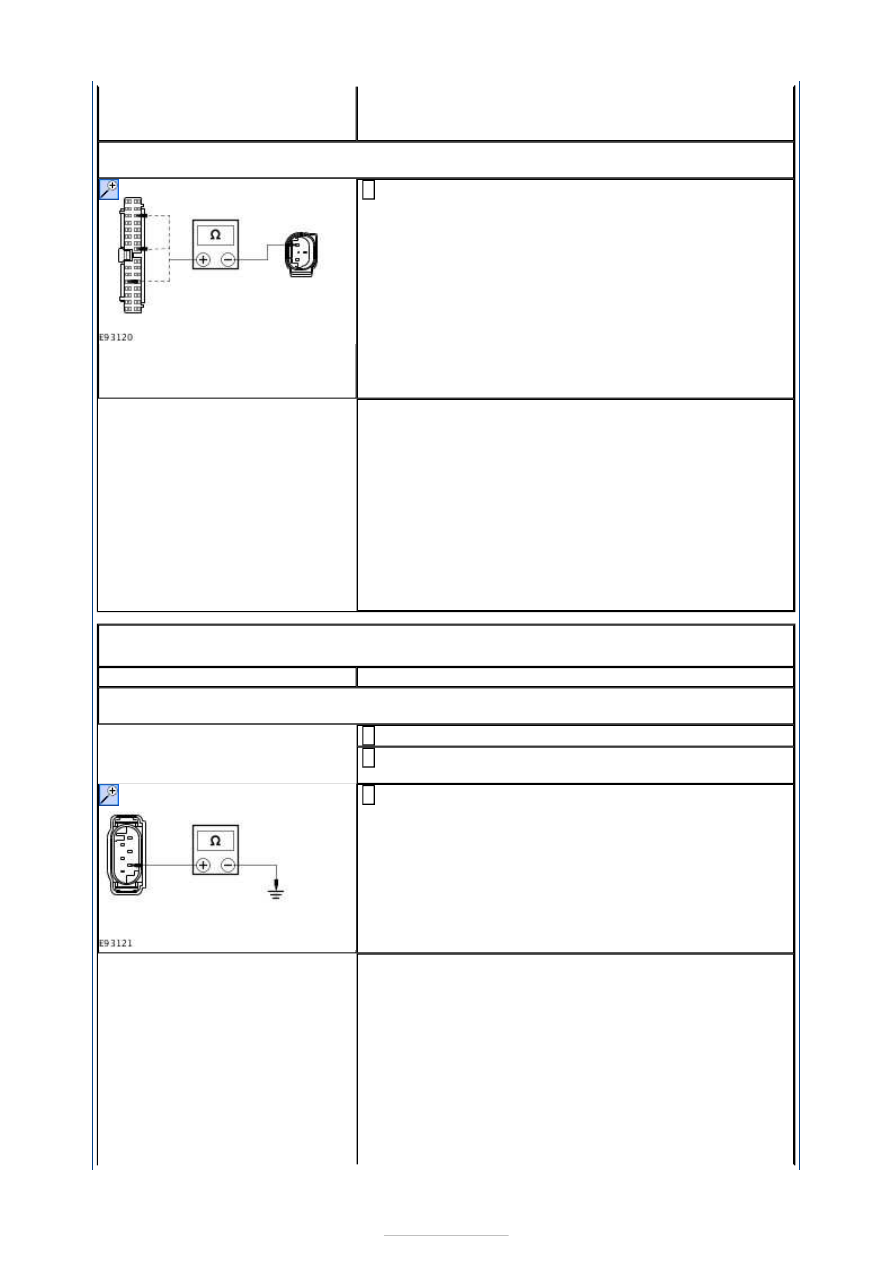
Measure the resistance between the following affected
vertical acceleration sensor connector pins, harness
side and the adaptive damping module connector pins,
harness side:
(Left front) C1CD07 pin 1, circuit VCD07A (BN/WH)
and C4CD01-B pin 10, circuit VCD07B (BN/WH).
(Right front) C1CD08 pin 1, circuit VCD08A (BU/GY)
and C4CD01-B pin 22, circuit VCD08B (BU/GY).
(Left rear) C4CD09 pin 1, circuit VCD09B (YE/VT)
and C4CD01-B pin 17, circuit VCD09B (YE/VT).
1
Is the resistance less than 1 ohm?
Yes
INSTALL new vertical acceleration sensors as required.
REFER to:
Vehicle Front Vertical Accelerometer
(204-05
Vehicle Dynamic Suspension, Removal and
Installation) /
Vehicle Rear Vertical Accelerometer
(204-05 Vehicle
Dynamic Suspension, Removal and Installation).
TEST the system for normal operation.
No
REPAIR the circuit. TEST the system for normal
operation.
PINPOINT TEST J : SUSPENSION HEIGHT SENSOR CIRCUIT - SHORT TO
GROUND
TEST CONDITIONS
DETAILS/RESULTS/ACTIONS
J1: CHECK THE SUSPENSION HEIGHT SENSOR SIGNAL RETURN CIRCUIT FOR SHORT
TO GROUND
Disconnect Adaptive Damping Module C4CD01-B.
1
Disconnect Affected Suspension Height Sensor
Connector.
2
Measure the resistance between the following affected
suspension height sensor connector pins, harness side
and ground:
(Left front) C5CD07 pin 4, circuit VCD10B (BN).
(Right front) C6CD08 pin 4, circuit VCD11B (GY/VT).
(Left rear) C7CD12 pin 4, circuit VCD12B (VT/WH).
(Right rear) C8CD13 pin 4, circuit VCD13B (GN/VT).
3
Is the resistance greater than 10,000 ohms (open circuit)?
Yes
INSTALL new suspension height sensors as required.
REFER to:
Front Suspension Height Sensor
(204-05
Vehicle Dynamic Suspension, Removal and
Installation) /
Rear Suspension Height Sensor
(204-05 Vehicle
Dynamic Suspension, Removal and Installation).
TEST the system for normal operation.
No
REPAIR the circuit. TEST the system for normal