Ford Galaxy / Ford S-MAX. Manual - part 27
 

  Index      Ford     Ford Galaxy / Ford S-MAX - service repair manual 2006 year


Search            


Content   ..  25  26  27  28   ..


Ford Galaxy / Ford S-MAX. Manual - part 27


Installation). 

No 

REINSTALL the strut and spring assemblies or shock absorbers. 

GO to B10

B10: CARRY OUT A ROAD TEST

Carry out a road test.  
REFER to: 

Road/Roller Testing

 (100-00 General Information, Description 

and Operation). 

Is the concern still evident? 
Yes 

REFER to: 

Noise, Vibration and Harshness (NVH)

 (100-04 Noise, Vibration 

and Harshness, Diagnosis and Testing). 

No 

Vehicle condition corrected. 

PINPOINT TEST C : VEHICLE LEAN  

TEST 

CONDITIONS

DETAILS/RESULTS/ACTIONS

C1: VEHICLE LEAN

Detach the load levelling shock absorbers from the wheel knuckles.  

Does the vehicle lean? 
Yes 

Install new rear springs. REFER to: 

Spring

 (204-02 Rear Suspension, 

Removal and Installation).TEST the system for normal operation. 

No 

CARRY OUT the Load-Levelling Shock Absorber Component Test in this 
section. 

PINPOINT TEST D : SHOCK ABSORBER SOLENOID CIRCUIT - SHORT TO 
GROUND 

TEST CONDITIONS

DETAILS/RESULTS/ACTIONS

D1: CHECK THE SHOCK ABSORBER SOLENOID SIGNAL RETURN CIRCUIT FOR SHORT 
TO GROUND

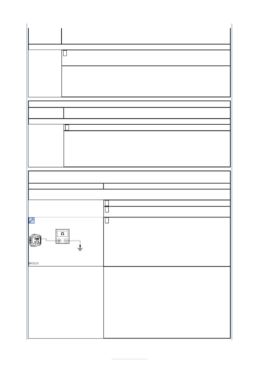
Disconnect Adaptive Damping Module C4CD01-B. 

Disconnect Affected Shock Absorber Solenoid 
Connector. 

Measure the resistance between the following affected 
shock absorber solenoid connector pins, harness side 

and ground: 

(Left front) C1CD03 pin 2, circuit RCD03B (VT/BN).  
(Right front) C1CD04 pin 2, circuit RCD04B (BU/OG). 

(Left rear) C4CD05 pin 2, circuit RCD05A (YE/BU).  
(Right rear) C4CD06 pin 2, circuit RCD06A (BU/BN). 

Is the resistance greater than 10,000 ohms (open circuit)? 
Yes 

INSTALL new front or rear shock absorbers as required. 
 
REFER to: 

Shock Absorber and Spring Assembly

 (204-

01 Front Suspension, Removal and Installation) /  

Shock Absorber and Spring Assembly

 (204-01 Front 

Suspension, Disassembly and Assembly) /  

Rear Shock Absorber

 (204-02 Rear Suspension, 

Removal and Installation). 
TEST the system for normal operation. 

No 

REPAIR the circuit. TEST the system for normal 
operation. 


PINPOINT TEST E : SHOCK ABSORBER SOLENOID CIRCUIT - SHORT TO 
POWER 

TEST CONDITIONS

DETAILS/RESULTS/ACTIONS

E1: CHECK THE SHOCK ABSORBER SOLENOID SIGNAL RETURN CIRCUIT FOR SHORT 
TO POWER

Disconnect Adaptive Damping Module C4CD01-B. 

Disconnect Affected Shock Absorber Solenoid 
Connector. 

Ignition switch in position II. 

Measure the voltage between the following affected 
shock absorber solenoid connector pins, harness side 

and ground: 

(Left front) C1CD03 pin 2, circuit RCD03B (VT/BN).  
(Right front) C1CD04 pin 2, circuit RCD04B (BU/OG). 

(Left rear) C4CD05 pin 2, circuit RCD05A (YE/BU).  
(Right rear) C4CD06 pin 2, circuit RCD06A (BU/BN). 

Is the voltage 0 volts? 
Yes 

INSTALL new front or rear shock absorbers as required. 
 
REFER to: 

Shock Absorber and Spring Assembly

 (204-

01 Front Suspension, Removal and Installation) /  

Shock Absorber and Spring Assembly

 (204-01 Front 

Suspension, Disassembly and Assembly) /  

Rear Shock Absorber

 (204-02 Rear Suspension, 

Removal and Installation). 
TEST the system for normal operation. 

No 

REPAIR the circuit. TEST the system for normal 
operation. 

PINPOINT TEST F : SHOCK ABSORBER SOLENOID CIRCUIT - OPEN 
CIRCUIT 

TEST CONDITIONS

DETAILS/RESULTS/ACTIONS

F1: CHECK THE SHOCK ABSORBER SOLENOID SIGNAL INPUT CIRCUIT FOR OPEN 
CIRCUIT

Disconnect Adaptive Damping Module C4CD01-B. 

Disconnect Affected Shock Absorber Solenoid 
Connector. 

Measure the resistance between the following affected 
shock absorber solenoid connector pins, harness side 

and the adaptive damping module C4CD01-B pins, 
harness side: 

(Left front) C1CD03 pin 1, circuit CCD03B (WH/BU) 
and C4CD01-B pin 6, circuit CCD03C (WH/BU).  
(Right front) C1CD04 pin 1, circuit CCD04B (GY/YE) 
and C4CD01-B pin 9, circuit CCD04C (GY/YE). 

(Left rear) C4CD05 pin 1, circuit CCD05A (GN/BU) 
and C4CD01-B pin 2, circuit CCD05B (GN/BU).  
(Right rear) C4CD06 pin 1, circuit CCD06A (VT/GY) 
and C4CD01-B pin 5, circuit CCD06B (VT/GY). 

Is the resistance less than 1 ohm? 
Yes 


GO to F2

.  

No 

REPAIR the circuit. TEST the system for normal 
operation. 

F2: CHECK THE SHOCK ABSORBER SOLENOID RETURN CIRCUIT FOR OPEN CIRCUIT

Measure the resistance between the following affected 
shock absorber solenoid connector pins, harness side 

and the adaptive damping module C4CD01-B pins, 
harness side: 

(Left front) C1CD03 pin 2, circuit RCD03B (VT/BN) 
and C4CD01-B pin 7, circuit RCD03C (VT/BN).  
(Right front) C1CD04 pin 2, circuit RCD04B (BU/OG) 
and C4CD01-B pin 8, circuit RCD04C (BU/OG). 

(Left rear) C4CD05 pin 2, circuit RCD05A (YE/BU) 
and C4CD01-B pin 1, circuit RCD05B (YE/BU).  
(Right rear) C4CD06 pin 2, circuit RCD06A (BU/BN) 
and C4CD01-B pin 4, circuit RCD06B (BU/BN). 

Is the resistance less than 1 ohm? 
Yes 

INSTALL new front or rear shock absorbers as required. 
 
REFER to: 

Shock Absorber and Spring Assembly

 (204-

01 Front Suspension, Removal and Installation) /  

Shock Absorber and Spring Assembly

 (204-01 Front 

Suspension, Disassembly and Assembly) /  

Rear Shock Absorber

 (204-02 Rear Suspension, 

Removal and Installation). 
TEST the system for normal operation. 

No 

REPAIR the circuit. TEST the system for normal 
operation. 

PINPOINT TEST G : VERTICAL ACCELERATION SENSOR CIRCUIT - SHORT 
TO GROUND 

TEST CONDITIONS

DETAILS/RESULTS/ACTIONS

G1: CHECK THE VERTICAL ACCELERATION SENSOR SIGNAL RETURN CIRCUIT FOR 
SHORT TO GROUND

Disconnect Adaptive Damping Module C4CD01-B. 

Disconnect Affected Vertical Acceleration Sensor 
Connector. 

Measure the resistance between the following affected 
vertical acceleration sensor connector pins, harness 

side and ground: 

(Left front) C1CD07 pin 1, circuit VCD07A (BN/WH).  
(Right front) C1CD08 pin 1, circuit VCD08A (BU/GY). 

(Left rear) C4CD09 pin 1, circuit VCD09B (YE/VT). 

Is the resistance greater than 10,000 ohms (open circuit)? 
Yes 

INSTALL new vertical acceleration sensors as required.  
REFER to: 

Vehicle Front Vertical Accelerometer

 (204-05 

Vehicle Dynamic Suspension, Removal and 
Installation) /  

Vehicle Rear Vertical Accelerometer

 (204-05 Vehicle 


Dynamic Suspension, Removal and Installation). 
TEST the system for normal operation. 

No 

REPAIR the circuit. TEST the system for normal 
operation. 

PINPOINT TEST H : VERTICAL ACCELERATION SENSOR CIRCUIT - SHORT 
TO POWER 

TEST CONDITIONS

DETAILS/RESULTS/ACTIONS

H1: CHECK THE VERTICAL ACCELERATION SENSOR SIGNAL RETURN CIRCUIT FOR 
SHORT TO POWER

Disconnect Adaptive Damping Module C4CD01-B. 

Disconnect Affected Vertical Acceleration Sensor 
Connector. 

Ignition switch in position II. 

Measure the voltage between the following affected 
vertical acceleration sensor connector pins, harness 

side and ground: 

(Left front) C1CD07 pin 1, circuit VCD07A (BN/WH).  
(Right front) C1CD08 pin 1, circuit VCD08A (BU/GY). 

(Left rear) C4CD09 pin 1, circuit VCD09B (YE/VT). 

Is the voltage 0 volts? 
Yes 

INSTALL new vertical acceleration sensors as required.  
REFER to: 

Vehicle Front Vertical Accelerometer

 (204-05 

Vehicle Dynamic Suspension, Removal and 
Installation) /  

Vehicle Rear Vertical Accelerometer

 (204-05 Vehicle 

Dynamic Suspension, Removal and Installation). 
TEST the system for normal operation. 

No 

REPAIR the circuit. TEST the system for normal 
operation. 

PINPOINT TEST I : VERTICAL ACCELERATION SENSOR CIRCUIT - OPEN 
CIRCUIT 

TEST CONDITIONS

DETAILS/RESULTS/ACTIONS

I1: CHECK THE VERTICAL ACCELERATION SENSOR SIGNAL INPUT CIRCUIT FOR OPEN 
CIRCUIT

Disconnect Adaptive Damping Module C4CD01-B. 

Disconnect Affected Vertical Acceleration Sensor 
Connector. 

Measure the resistance between the following affected 
vertical acceleration sensor connector pins, harness 

side and the adaptive damping module C4CD01-B pin 
13, circuit LCD02K (YE/GN): 

(Left front) C1CD07 pin 3, circuit LCD02F (YE/GN).  
(Right front) C1CD08 pin 3, circuit LCD02E (YE/GN). 

(Left rear) C4CD09 pin 3, circuit LCD02J (YE/GN). 

Is the resistance less than 1 ohm? 
Yes 

GO to I2

.  


Content   ..  25  26  27  28   ..