Ford Galaxy / Ford S-MAX. Manual - part 1


  Index      Ford     Ford Galaxy / Ford S-MAX - service repair manual 2006 year


Search                


Content   ..  1  2  3   ..


Ford Galaxy / Ford S-MAX. Manual - part 1


General Information - About This Manual

S-MAX/Galaxy 2006.5 (02/2006-)


Print


Description and Operation 

Introduction 

This manual covers diagnosis and testing and repair procedures. 

It is structured into groups and sections, with specific system sections collected together 
under their relevant group. 

A group covers a specific portion of the vehicle. The manual is divided into five groups, 
General Information, Chassis, Powertrain, Electrical and Body and Paint. The number of the 
group is the first number of a section number. 

Within Etis, the navigation tree will list the groups. After selecting a group the navigation 
tree will then list the sections within that group. Each section has a contents list detailing 
Specifications, Description and Operation, Diagnosis and Testing, General Procedures, 
Disassembly and Assembly, Removal and Installation. 

References to 

LH (left-hand)

 and 

RH (right-hand)


All 

LH

 and 

RH

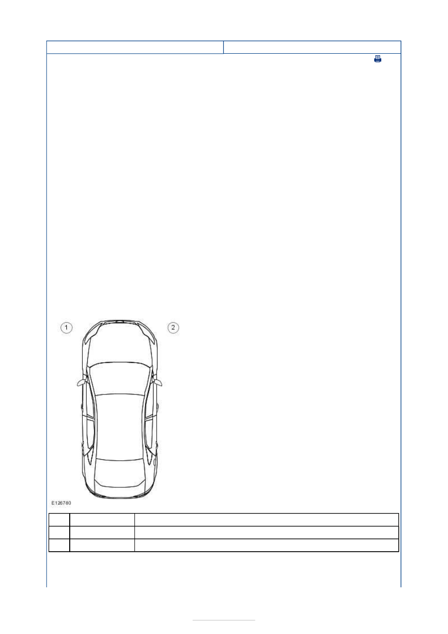
 references to the vehicle are taken from a position sitting in the driver seat 

looking forward. 

Vehicle 

LH

 and 

RH

 definition 


Description 

LH 

RH 

All 

LH

 and 

RH

 references to the engine are taken from a position at the flywheel looking 

towards the crankshaft front pulley. 

Powertrain 

LH

 and 

RH

 definition 

Item

1

2


Part Number

-

-


Description 

front 

right 

rear 

left 

How to use Repair Procedures 

This manual has been written in a format that is designed to meet the needs of technicians 
worldwide. It provides general descriptions for accomplishing repair work with tested and 
effective techniques. 

Important Safety Instructions 

Appropriate service methods and correct repair procedures are essential for the safe, 
reliable operation of all motor vehicles as well as the personal safety of the individual 
carrying out the work. 

Anyone who departs from the instructions provided in this manual must first establish that 
personal safety or vehicle integrity is not compromised by the choice of method, tools or 
components. 

Warnings, Cautions and Notes in This Manual 

WARNING: Warnings are used to indicate that failure to follow a procedure correctly 

may result in personal injury. 

CAUTION: Cautions are used to indicate that failure to follow a procedure correctly 

may result in damage to the vehicle or equipment being used. 
NOTE: Notes are used to provide additional essential information required to carry out a 
complete and satisfactory repair. 

Generic warnings or cautions are in their relevant description and operation procedure 
within section 100-00. If the generic warnings or cautions are required for a procedure, 
there will be a referral to the appropriate description and operation procedure. 

If a warning, caution or note only applies to one step, it is placed at the beginning of the 
specific step. 

Item

1

2

3

4


Part Number

-

-

-

-

Trustmark Authoring Standards (TAS) Repair Procedures 

NOTE: TAS style procedures can be identified by steps that have no accompanying step 
text and the magenta color of the electrical connectors and fasteners such as nuts, bolts, 
clamps or clips. 

A TAS removal and installation procedure uses a sequence of color illustrations to indicate 
the order to be followed when removing/disassembling or installing/assembling a 
component. 

Many of the TAS procedures will have the installation information within the removal steps. 
These procedures will have the following note at the beginning of the procedure:  

NOTE: Removal steps in this procedure may contain installation details. 

Reuse of fasteners and seals and gaskets 

The following list details the general policy for the reuse of fasteners and seals and gaskets. 

Types of self-locking nuts and bolts 

NOTE: There are more types of self-locking fasteners available than shown in following 
illustration. 


Description 

Completely coated self-locking bolt 

Partially coated self-locking bolt 

Self-locking bolt with a locking washer 

Self-locking nut with a plastic locking insert 

Self-locking nut with thread deformation (3 dents) 

Self-locking nut with thread deformation (squeeze of thread to oval 
shape) 

Self-locking nut with integrated locking ring 

All types of seals and gaskets must be discarded and new seals and gaskets installed 
unless otherwise stated within the procedure.  
Nuts and bolts with a chemical coating for locking and/or sealing and/or antiseize must 
be discarded unless the procedure advises to reapply the coating with a specified 

Item

1

2

3

4

5

6

7


Part Number

-

-

-

-

-

-

-

material.  
Nuts and bolts with a mechanical locking such as thread inserts, thread deformation or 
locking washers must be discarded and new nuts and bolts installed unless otherwise 
stated within the procedure.  
Torque to yield bolts must be discarded and new torque to yield bolts installed unless 
otherwise stated within the procedure, recognizable by a tightening torque with more 
than one stage together with a torque angle. 

Specification data 

Specification procedures will only contain technical data that is not already part of a repair 
procedure. 

Sequence of tasks 

If components must be removed or installed in a specific sequence, the sequence will be 
identified numerically in a graphic and the corresponding text will be numbered accordingly. 

Special Tools, Equipment, Materials and Torque Figures 

Special tools will be shown with the tool numbers in the illustration. The special tool 
numbers, general equipment, materials and torque figures used for the procedure step will 
be shown in the text column.  

TAS Graphics 

Colors used in the graphic are as follows: 

Blue - Component to be removed/installed or disassembled/assembled.  
Green and Brown - Additional components that need to be removed/installed or 
disassembled/assembled prior to the target component.  
Yellow - Component that is touched or affected in a way but remains in the vehicle. It 
may be detached, attached, moved, modified, checked, adjusted etc.  
Magenta - Electrical connectors and fasteners such as nuts, bolts, clamps and clips.  
Pale Blue - Special tool(s) and general equipment. 

One illustration may have multiple steps assigned to it. 

Numbered pointers are used to indicate the number of electrical connectors and fasteners 
such as nuts, bolts, clamps and clips. 

Items in the illustration can be transparent or use cutouts to show hidden details. 


Content   ..  1  2  3   ..