Ford Falcon. Manual - part 253
 

  Index      Ford     Ford Falcon - service repair manual 2002-2005 year


Search            


Content   ..  251  252  253  254   ..


Ford Falcon. Manual - part 253


307-05-15 

Automatic Transmission External Controls 

307-05-15

REMOVAL AND INSTALLATION (Continued)

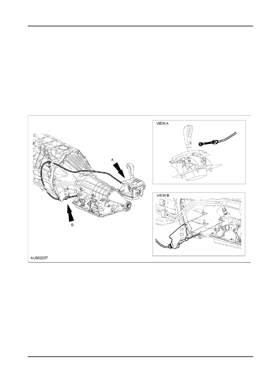
Selector Lever Cable

Removal
1.  Release locking tab from the Transmission Cable

Mount.

2.  Disconnect the cable from the housing.
3.  Use a screwdriver to release the cable push rod

from the cable arm.

Installation
1.  To reassemble simply push the cable end fitting

back into the pin.

I6 Selector Cable

G77045 en

307-05-16 

Automatic Transmission External Controls 

307-05-16

REMOVAL AND INSTALLATION (Continued)

V8 Selector Cable

G77045 en

308-01-1 Clutch 308-01-1

SECTION : 308-01 Clutch

VEHICLE APPLICATION : 2003.0 BA Falcon
CONTENTS  

PAGE

SPECIFICATIONS

 Specifications  .........................................................................................................................308-01-2

DESCRIPTION AND OPERATION

 Clutch  .....................................................................................................................................308-01-3

 Introduction 


..........................................................................................................................308-01-3

 Clutch 

Function 


....................................................................................................................308-01-3

DIAGNOSIS AND TESTING

 Clutch  .....................................................................................................................................308-01-6

 Symptom 

Chart 


....................................................................................................................308-01-6

GENERAL PROCEDURES

  Pressure Plate Inspection  ......................................................................................................308-01-8

  Clutch Disc Inspection  ...........................................................................................................308-01-8

  Clutch Pressure Plate Adjustment (XR6 Turbo Variant)  ........................................................308-01-8

REMOVAL AND INSTALLATION

  Disc and Pressure Plate  ........................................................................................................308-01-9

  Flywheel — I6 (all variants including XR6 Turbo)  ................................................................308-01-10

  Flywheel — All V8 Vehicles (incl XR8 & GT)  .......................................................................308-01-11

  Pilot Bearing — All Vehicles  ................................................................................................308-01-11

DISASSEMBLY AND ASSEMBLY

  Flywheel Auto Flex-Plate (XR6 Turbo only)  .........................................................................308-01-13

  Ring Gear — All Vehicles except XR6 Turbo  ......................................................................308-01-13

  Ring Gear — XR6 Turbo only  ..............................................................................................308-01-14

308-01-2 Clutch 308-01-2

SPECIFICATIONS

Torque Specifications

Description

Nm

CSC to clutch housing

9.5

CSC to pipe fitting nut

14

CSC Bleed screw

8

Clutch pressure plate to flywheel

I6

20

V8

48

Flex plate to flywheel disc (Turbo only)

60

Flywheel to crankshaft

I6

75

V8

80

Dowel insertion depth in flywheel

(Proud of friction face)

I6

8mm

XR6 Turbo

10.5mm

V8

11.5mm

NOTE: The V8 flywheel is designed so that the dowel

will bottom out at the correct insertion depth.

G86726 en


Content   ..  251  252  253  254   ..