Ford Falcon. Manual - part 207
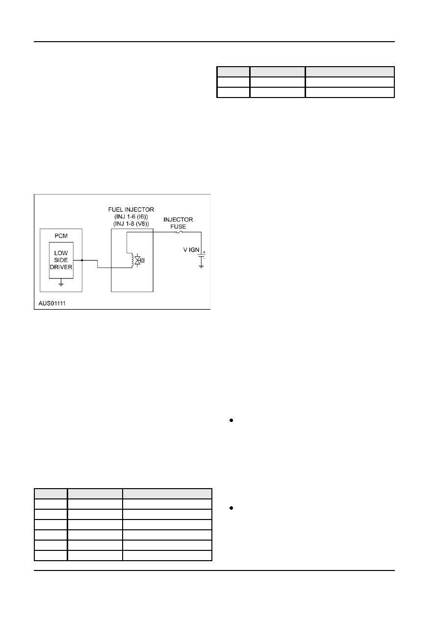
303-14-42
Powertrain Control Management
303-14-42
DESCRIPTION AND OPERATION (Continued)
PCM Pin A3................................... Injector 6
DTC
Test Mode
Condition
P0207
KOEO, Cont.
INJ7 circuit malfunction
Connections (V8)
P0208
KOEO, Cont.
INJ8 circuit malfunction
PCM Pin A14................................. Injector 1
PCM Pin A3................................... Injector 2
Failure Mode
PCM Pin A8................................... Injector 3
Should a fuel injector fail the engine may run rough, a
PCM Pin A10................................. Injector 4
Diagnostic Trouble Code (DTC) will be logged in
memory for the failed injector and subsequent
PCM Pin A4................................... Injector 5
unexpected changes in the air-fuel ratio.
PCM Pin A7................................... Injector 6
In the unlikely event that all the fuel injectors fail
PCM Pin A15................................. Injector 7
simultaneously, the vehicle will not run. The
PCM Pin A42................................. Injector 8
appropriate DTC will be reported to indicate failure of
the individual fuel injectors.
Circuit
Testing
The fuel injectors are tested continuously during
vehicle operation (cont.) and whenever a Key On
Engine Off (KOEO) test is performed.
Injector Fouling
Over time, sulphur and other trace elements in petrol
can build-up on the injector spray plate and around
the nozzle. The quality of the fuel plays an important
part in minimising this fouling of the fuel injectors.
Fouling affects both the spray pattern and the volume
of fuel injected. Incorrect spray pattern will cause poor
atomisation and vaporisation of the fuel, which results
in poor combustion, rough idle and high hydrocarbon
and carbon monoxide emissions.
Maintenance
Fouling of the fuel injectors is a common condition
that should be suspected if the engine is running
The fuel rail must be removed to replace the fuel
rough or hesitation during cold acceleration.
injectors. The procedure is described in Fuel Rail in
the ‘Removal and Installation’ section. The fuel
Injector Test
injectors have a fixed orifice size and cannot be
adjusted
1. Disconnect the harness from the fuel injector
connector.
NOTE: If any, or all, of the fuel injectors are replaced,
the Keep Alive Memory (KAM) must be reset to
2. Measure the resistance across the fuel injector
ensure the adaptive idle strategy does not use the
connector terminals using a suitable multimeter.
previous adaptive values. Refer to Resetting The
Replace the fuel injector if not within specification.
Powertrain Control Module.
Repeat the procedure for each fuel injector.
Fuel Injector Solenoid Resistance
Diagnosis
Specification
13.5 to 16.0
Ω
Diagnostic Trouble Codes (DTC) are retrieved through
the diagnostic connector using the WDS tester. Fault
3. Turn the ignition key to the ON position. Do not
Finding Tables for DTCs are in the ‘Diagnosis’
start the engine. Positive power should be applied
section.
to the fuel injectors from the PCM Power Relay.
4. On the harness, measure the voltage between the
DTCs applicable to the fuel injectors are shown in the
positive connector terminal (red wire) and ground
following table.
using a suitable multimeter. Repeat the procedure
DTC
Test Mode
Condition
for each fuel injector.
P0201
KOEO, Cont.
INJ1 circuit malfunction
Fuel Injector Voltage Specification
P0202
KOEO, Cont.
INJ2 circuit malfunction
12 Volts DC
P0203
KOEO, Cont.
INJ3 circuit malfunction
5. Check the harness for open circuits and short
circuits.
P0204
KOEO, Cont.
INJ4 circuit malfunction
P0205
KOEO, Cont.
INJ5 circuit malfunction
P0206
KOEO, Cont.
INJ6 circuit malfunction
G98133 en