Ford Falcon. Manual - part 102
211-05-5 Steering
Column
Switches 211-05-5
DIAGNOSIS AND TESTING (Continued)
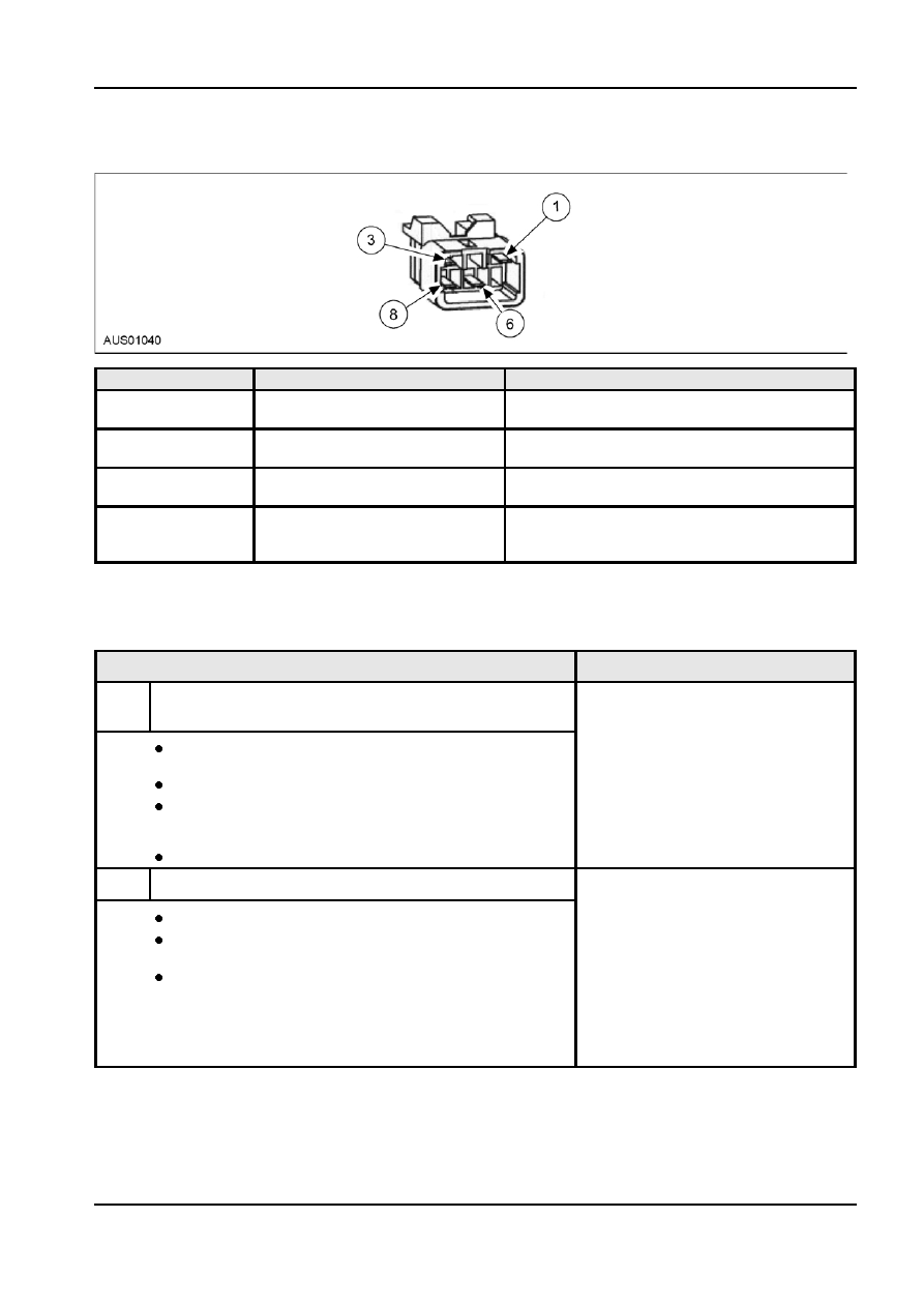
Pedal Adjust Switch Connector and Pinout
Pin Number(s)
Circuit Designation/Description
Normal Condition/Measurement
1
Pedal Circuits Batery +VE-
Yellow
3 Pedal Circuits Ground
Black
6 Pedal Circuits Motor -VE- (Back)
Light Blue / Orange Stripe
8 Pedal Circuits Motor +VE-
(Forward)
Light Blue / Black Stripe
Pinpoint Tests
PINPOINT TEST A : IGNITION SWITCH IS INOPERATIVE (NO POWER IN ACC/ON OR START)
Test Step
Result / Action to Take
A1
CHECK CONTINUITY OF IGNITION SWITCH AND LOCK
HOUSING
Remove steering column shrouds from vehicle. Refer to Section
Yes
211-04.
Check wiring for ignition switch circuit. Please
refer to wiring diagrams for details of circuits.
Disconnect ignition switch connector.
No
With car keys inserted, use a multimeter to check the continuity of the
Go to A2.
ignition switch for the various positions (ACC, ON) at the ignition
switch connector.
Is continuity of ignition switch accurate for each position?
A2
CHECK FUNCTIONALITY OF LOCK BARREL
Remove lock barrel from steering column.
Yes
Install a new ignition switch. Refer to ignition
Check functionality of lock barrel: rotate key in barrel and confirm that
switch installation and removal section. Repeat
the shaft in barrel is turned when key is turned.
test A1 to confirm operation of system.
NOTE: Ignition switch is integral with column.
Is lock barrel functional?
Need to replace column assembly. See Section
211-04.
No
Install a new lock barrel. Repeat test A1 to
confirm operation of ignition switch.
G57381 en