Ford Falcon. Manual - part 100
211-04-12 Steering
Column 211-04-12
DISASSEMBLY AND ASSEMBLY
1. The clockspring is clipped into the multi-function
Setting the Steering Column
switch, and can be removed by deflecting and
Adjustment Clamp
releasing the three retaining clips. Remove the
two electrical connectors from the wire harness
Assembly
bracket.
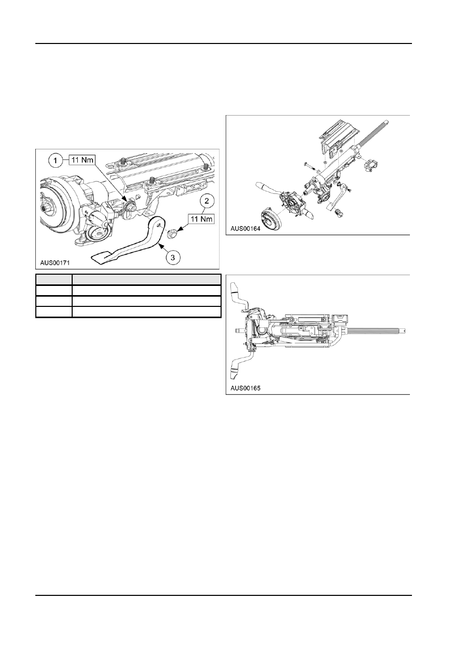
1. Remove the bolt and washer securing the black
plastic adjustment lever to the serrated clamping
nut.
2. Remove the lever from the clamp nut.
2. Remove the three screws which secure the
multi-function wash/wipe/indicator/headlight
switch. Slide the lever-lock connector off the tag
of the wire harness bracket.
Item
Description
1
Serrated Clamping Nut
2
Bolt
3
Adjustment Lever
3. Slacken off and re-tighten the clamp nut to 11Nm
torque.
4. Reposition the lever on the clamp-nut ensuring
the serrations mesh correctly, and the lever is in
the fully closed position. i.e. the main arm of the
lever is parallel to the centreline of the steering
column
5. Hold the lever and replace the washer and bolt.
Tighten the bolt to 11Nm torque.
3. Remove the electrical connector from the PATS
unit.
Adjustable Steering Column
4. Remove the screw that attaches the PATS unit to
Disassembly
the ignition lock housing. Slide the PATS unit off
the ignition lock housing.
NOTE: The degree of disassembly required will
NOTE: The ignition illumination globe in the PATS
depend on the nature of the repair or the component
unit is not serviceable as a separate item.
which is to be replaced. Disassembly instructions are
given below, but it may not be necessary to carry out
5. Remove the bolt and washer securing the
all steps to effect the required repairs. These
adjustment lever, and remove the lever. Undo
instructions refer to a steering column that has been
serrated clamping nut and remove the plastic
completely removed from the vehicle.
thrust washer.
NOTE: The bolt, serrated clamp nut, and clamp
bolt use a special double start thread, and cannot
be replaced with conventional metric fasteners.
6. Remove the counter balance spring, clamp bolt
and clamping spacer.
7. Remove the alloy mounting bracket.The column is
now completely disassembled.
NOTE: The upper and lower steering shafts and
bearings are not serviceable. The upper shaft and
A12351 en