Ford Falcon. Manual - part 99
211-04-8 Steering
Column 211-04-8
REMOVAL AND INSTALLATION (Continued)
6. Disconnect the 2 wire harnesses from the
9. Remove the four bolts retaining the alloy steering
clockspring.
column mounting bracket onto the instrument
panel, and completely remove the column from
the vehicle.
NOTE: The four bolts are retained in the alloy
mounting bracket using special fibre retaining
washers. Make sure all these washers are in
place before re-installing the steering column. If
one or more of the washers are missing, the alloy
mounting bracket may become distorted,
adversely affecting the column adjustment
mechanism and column break-away mechanism .
Delete all the washers from the installation if one
or more of the fibre washers are missing.
Installation
1. Before re-installing the steering column, check
that the front wheels are in the straight ahead
position.
2. Check that the clockspring has been centralized
on the steering column. See Section 211-04-13.
3. Fit the lower steering column shaft into the
connector tube on the floor plate. Loosely fit the
M8 flanged head bolt.
4. To align the alloy mounting bracket to the steering
column, close the adjustment lever so that the
clamping mechanism is just nipped up. The alloy
bracket should still be able to rotate by hand so
that it can align to the instrument panel. Secure
the four M8 mounting bracket bolts to the
instrument panel and torque to 18Nm.
NOTE: The four bolts are retained in the alloy
mounting bracket using special fibre retaining
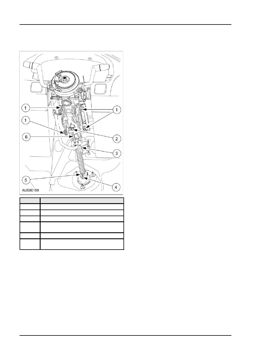
Item
Description
washers. Make sure all these washers are in
1
Four mounting bolts. Torque to 18 Nm.
place before re-installing the steering column. If
2
Two clockspring connectors
one or more of the washers are missing, the alloy
mounting bracket may become distorted,
3
One release tab for lever lock connector
adversely affecting the column adjustment
4
Pull back safety clip before removing the
mechanism and column break-away mechanism .
aluminum shaft
Delete all the washers from the installation if one
5
Torque bolt to 25 Nm
or more of the fibre washers are missing.
6
Two release tabs for ignition wiring lever
5. Torque the M8 flanged head bolt in the lower
lock connector
steering column shaft to 25Nm.
7. Disconnect the ignition wire harness lever-lock
6. Connect the lever lock connectors for the multi
connector. The lever has two retaining tabs that
function switch, and ignition wiring.
keep the lever locked in place. These must be
7. Connect the two clockspring connectors.
disengaged before the lever can be rotated.
8. Refit the shrouds. See Section 211-04-5.
8. Disconnect the multi-function switch wire harness
9. Refit the steering wheel and Driver Air Bag. See
lever-lock connector. The lever has a single
Section 211-04-09 & Section 211-04-10.
retaining tab that keeps the lever locked in place.
This must be disengaged before the lever can be
10. Adjust the steering column through its full range to
rotated.
ensure the movement is smooth.
11. Re-connect the battery.
A12346 en