Ford Falcon. Manual - part 61
206-00-6
Brake System — General Information
206-00-6
DIAGNOSIS AND TESTING
Rotor Wear and Runout
Brake System
Remove the wheel to inspect the rotor.
Special Tool(s)
Check the rotor for scoring. Minor scores need not
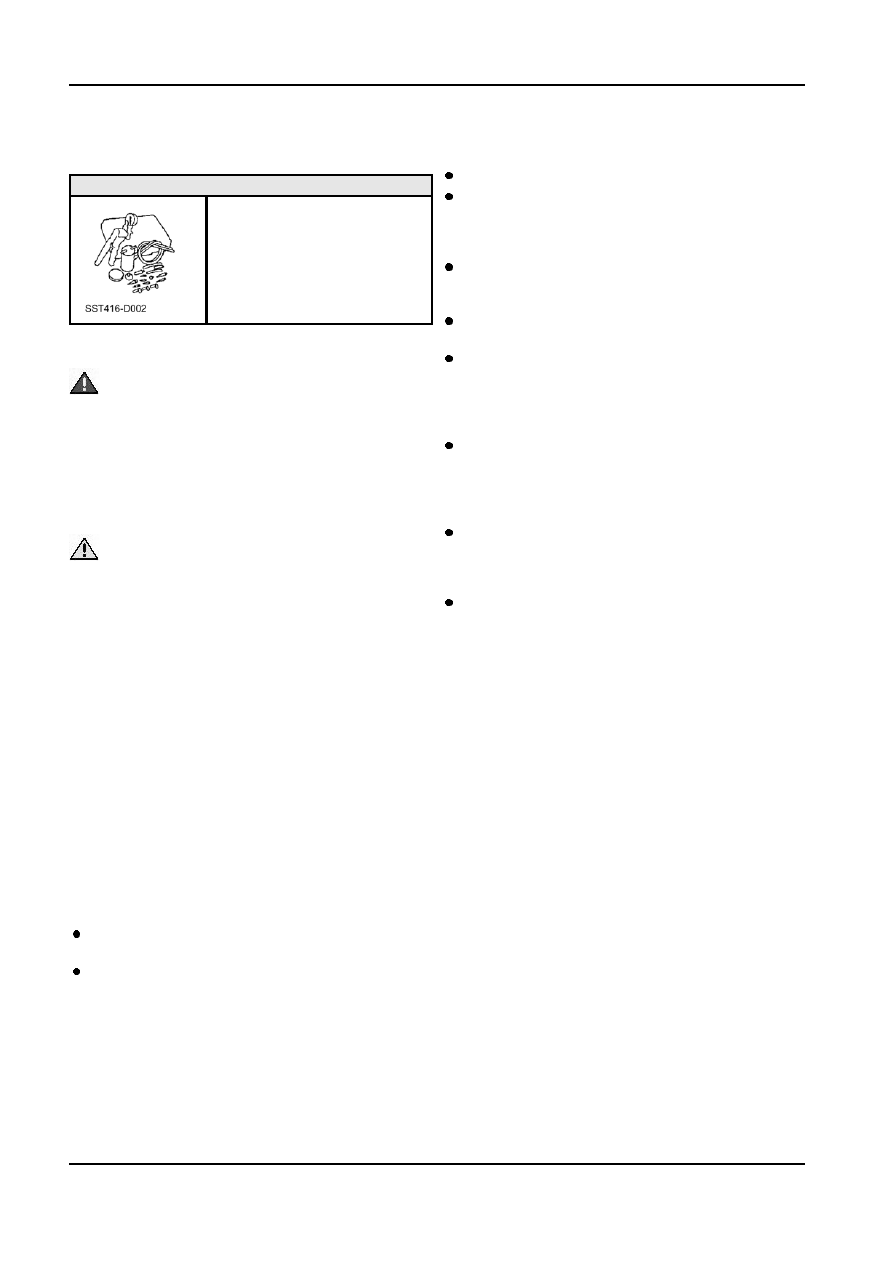
Vacuum Pump
be removed. If the rotor is excessively scored,
416-D002 (D95L-7559-A) or
refinish it in accordance with the Specifications or
equivalant
replace the rotor.
When checking front rotor runout, be sure to take
the wheel bearing end play into account. Remove
the rotor if necessary.
Front wheel bearing end play is critical and must
be within specifications.
Inspection and Verification
To check the rear rotor run-out either apply a load
to the end of the axle shaft to remove the end
WARNING: Brake fluid contains polyglycol
float in the bearing or remove the axle shaft and
ethers and polyglycols. Avoid contact with eyes.
rotor assembly from the housing and check the
Wash hands throughly after handling. If brake
run-out by mounting the axle on its centres.
fluid contacts eyes, flush eyes with running water
Clamp a dial indicator to the caliper housing so
for 15 minutes. Get medical attention if irritation
that the stylus contacts the braking surface of the
persists. If taken internally, drink water and
rotor approximately 32 mm from the outer edge
induce vomiting. Get medical attention
for a front rotor or 3mm from the outer edge for a
immediately. Failure to follow these instructions
rear rotor.
may result in personal injuiry.
Rotate the rotor and take an indicator reading. If
the total lateral run-out exceeds 0.08 mm for a
CAUTION: Do not spill brake fluid onto
front rotor or 0.05 mm for a rear rotor, resurface
painted surfaces. If spilled, wipe it up
or replace the rotor.
immediately.
Refer to Specifications section for refinishing
NOTE: Always check the fluid level in the brake
specifications. Refer to Section 206-03 or Section
master cylinder before carrying out the test
206-04 for information regarding rotor
procedures. If the fluid level is not above the MIN line,
replacement.
add High Performance Motor vehicle brake fluid
meeting Ford specification ESZ-M6C55-A or
Disc Thickness Variation
equivalant Super DOT4 fluid.
This is the variation in thickness between the two
NOTE: Prior to carrying out any diagnosis, verify that
braking surfaces of the rotor measured
the brake warning indicator is functional. Apply the
circumferentially.
parking brake. If the brake warning indicator does not Disc thickness variation may cause a pulsating pedal
illuminate, refer to Brake fail warning light component
or noisy operation.
test.
Two methods may be used to measure thickness
NOTE: The primary indicators of brake system
variation.
concerns are a change in the feeling through the
A micrometer can be used to measure the rotor
brake pedal, the brake warning indicator, and the
thickness at 12 points approximately 30 degrees apart
brake fluid level. If a problem exists, refer to the
and 25 mm from the outer edge of the rotor.
following diagnosis guide.
The other method is to mount the rotor on a precision
lathe designed for machining disc brake rotors. Attach
Pad Wear
two dial indicators, one each side of the rotor, so that
Remove the wheel to inspect the pads. Refer
the stylus of each indicator contacts the rubbing
Warning under Service Precautions.
surface approximately 25 mm from the outer edge of
the rotor.
If a lining has worn to a thickness of 1.0 mm at
any one of three measuring locations or if there is Zero both indicators and rotate the rotor while
more than 3 mm taper from end to end replace all watching both dials. If the total readings of both
(4) pad assemblies on both front or both rear
indicators exceed the specified limit for thickness
wheels to maintain even braking. Refer to Section variation, the rotor must be refinished or replaced.
206-03 or Section 206-04 for replacement of
parts.
G17361 en