Ford Falcon. Manual - part 59
 

  Index      Ford     Ford Falcon - service repair manual 2002-2005 year


Search            


Content   ..  57  58  59  60   ..


Ford Falcon. Manual - part 59


205-05-8 

Rear Drive Halfshafts 

205-05-8

DISASSEMBLY AND ASSEMBLY (Continued)

3.  If reinstalling the original CV joint, mark the

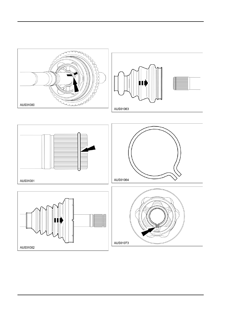
2.  Install the inboard halfshaft boot. This is most

outboard CV joint and halfshaft to make sure of

easily achieved by inserting the large opening

correct installation.

from the outboard end. And sliding the boot along

the shaft to the other side.

4.  Use a soft-face hammer to separate the outboard

CV joint by gently tapping it off the halfshaft.

3.  Replace the inboard joint retainer ring. A retainer

on the shaft is not required.

5.  Remove the halfshaft retainer-circlip and discard.

6.  Slide the outboard halfshaft boot off the halfshaft.

Assembly V8 Inboard

1.  Lubricate the inboard and outboard CV joint with

joint grease.

G96425 en

205-05-9 

Rear Drive Halfshafts 

205-05-9

DISASSEMBLY AND ASSEMBLY (Continued)

4.  Use a soft-face hammer to install the inboard CV

2.  Position the halfshaft boot.

joint by gently tapping it onto the halfshaft.

3.  Install the snap ring.

5.  Remove any excess grease on the mating

surfaces and slide the inboard halfshaft joint boot

forward onto the inboard CV joint.

6.  Remove any excess air trapped in the inboard

halfshaft boot using a cloth covered screwdriver

after adjusting the outboard halfshaft boot

spacing.

4.  Using a soft face hammer, install the halfshaft on

the joint.

7.  Ensure that the small end of the boot is positioned

as shown in adjacent picture - that is, such that

the small end is located in the groove in the shaft

and that the shape of the shaft adjacent to the

boot is as shown.

8.  The air pressure within the boot is self -adjusting

for this type of boot.

Assembly V8 Outboard and I6 Inboard & Outboard

1.  Slide the small boot clamp onto the shaft.

5.  Position the halfshaft boot.

G96425 en

205-05-10 Rear 

Drive 

Halfshafts 205-05-10

DISASSEMBLY AND ASSEMBLY (Continued)

6.  Ensure that the small end of the boot is positioned

as shown in adjacent picture - that is, with one of

the small grooves visible.

7.  Remove any excess air trapped in the halfshaft

boot using a cloth covered screwdriver after

adjusting the halfshaft boot spacing.

8.  Using the special tool, install two new joint boot

clamps. The outboard joint has an ABS rotor

attached as shown.

9.  Install the halfshaft. Refer Section 205-02b.

G96425 en

206-00-1 

Brake System — General Information 

206-00-1

SECTION : 206-00 Brake System — General

Information

VEHICLE APPLICATION : 2003.0 BA Falcon
CONTENTS  

PAGE

SPECIFICATIONS

 Specifications  .........................................................................................................................206-00-2

DESCRIPTION AND OPERATION

 Brake System  .........................................................................................................................206-00-4

  Load Proportioning Valve 1 Tonne Ute  ................................................................................206-00-5

DIAGNOSIS AND TESTING

 Brake System  .........................................................................................................................206-00-6

  Inspection and Verification  ...................................................................................................206-00-6

 Symptom 

Chart 


....................................................................................................................206-00-7

 Components 

Tests 


...............................................................................................................206-00-9

GENERAL PROCEDURES

  Hydraulic System Bleeding  ..................................................................................................206-00-11

  Manual System Bleeding  .....................................................................................................206-00-11

  System Pressure Bleeding  ...................................................................................................206-00-11

 Service Precautions  .............................................................................................................206-00-12

  Changing Brake Fluid  ..........................................................................................................206-00-12

  Brake Pedal Clearance Check  .............................................................................................206-00-12

 Caliper  ..................................................................................................................................206-00-12

  Brake System Leak Check ...................................................................................................206-00-13


Content   ..  57  58  59  60   ..