Ford Ranger EV. Electric Manual - part 33
 

  Index      Ford     Ford Ranger EV - Electric manual 1998 year


Search            


Content   ..  31  32  33  34   ..


Ford Ranger EV. Electric Manual - part 33


LESSON 4: SPECIAL SERVICE TOOLS AND PROCEDURES

4-5

Traction Battery High Voltage (HV) Lockout and
Diagnostic Tool

ER139-A

Traction Battery High Voltage (HV) Lockout and Diagnostic Tool

It is a dual-purpose tool that allows the vehicle to be powered up

when performing current leakage diagnostics.

It is used as a safety device when the Traction Inverter Module

(TIM) is disconnected from the traction battery.

It is connected to the HV two-pin connector located at the rear of

the traction battery pack.

LESSON 4: SPECIAL SERVICE TOOLS AND PROCEDURES

4-6

Auxiliary Interlock Tool

ER140-A

Auxiliary Interlock Tool

It is used to close the interlock loop on the vehicle during

diagnostics.

– After disconnecting the traction battery high-voltage auxiliary

load connector at the right front side of the traction battery,

connect this tool between the traction battery and in-line

interlock connector C1948 located behind the high voltage

power distribution box (HVPDB).

LESSON 4: SPECIAL SERVICE TOOLS AND PROCEDURES

4-7

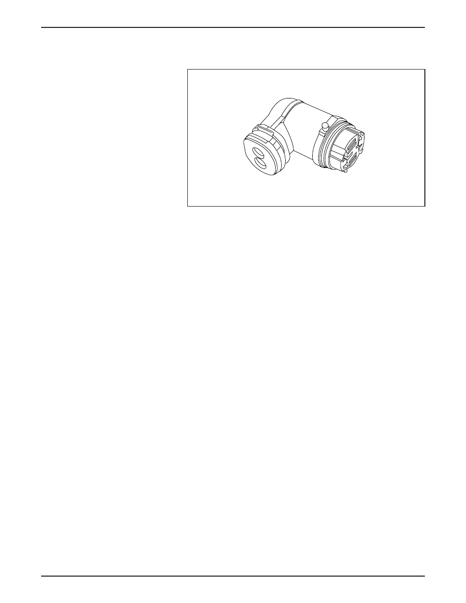
Power Steering Interlock Tool

Power Steering Interlock Tool

The Power Steering Interlock Tool connects to the power steering

connector pigtail from the high voltage power distribution box

(HVPDB) to the power steering assembly.

It is used to close the interlock loop when performing current

leakage diagnostics.

In-Line Bypass Battery Module

ER141-A

ER142-A

In-Line Bypass Battery Module

The In-Line Bypass Battery Module is used when traction battery

module replacement is required.

It is inserted into the traction battery pack at the location where the

replacement module is to be installed.

The vehicle is then connected to the power control station (PCS),

and the traction battery pack is brought up to full charge.

The In-line Bypass Battery Module tool is then removed and the

new, fully charged battery module is installed into the traction

battery pack.

LESSON 4: SPECIAL SERVICE TOOLS AND PROCEDURES

4-8

Electric Motor/Transaxle Test Box

Electric Motor/Transaxle Test Box

The Electric Motor/Transaxle Test Box is used to perform tests that

are necessary for diagnosing internal electric motor/transaxle

components.

The Electric Motor/Transaxle Test Box will perform the following

component tests on the electric motor/transaxle.

NOTE: If a problem with one of these internal components is

identified and confirmed, the entire electric motor/transaxle will

require replacement.

Motor Speed Sensor Operation – The Electric Motor/Transaxle

Test Box will confirm the operation of the speed sensors within the

motor assembly. Working through the transaxle connector located

on the top of the motor assembly next to the three power leads, the

tester directly interfaces with the speed sensors. Spinning the

wheels by hand will cause lights to alternately illuminate on the

tester. If there is a problem with the sensors, either one or both

lights will not illuminate.

Motor Temperature Sensor – The Electric Motor/Transaxle Test

Box provides an interface for a digital voltmeter to directly read the

resistance of the temperature sensor. This resistance will

correspond with a temperature in degrees Celsius. A resistance

value that falls outside of the range specified may indicate that the

sensor has either shorted or is an open circuit.

ER150A-A

1U14 TRANSAXLE TEST BOX

Lube Pump

P
O

W

E
R

P
O

W

E
R

RPM Sensor

On

Pressure

Hi

Hi

Low

Low

Channel A

C
h
a
n
n
e

l

Channel B

Sensor

Temp


Content   ..  31  32  33  34   ..