Ford Focus RS (2011 year). Instruction - part 84
Rear Bumper Cover — 2.5L Duratec-ST (VI5)
General Equipment
5 mm Drill Bit
General Equipment
Blind Rivet Gun
Electric Drill
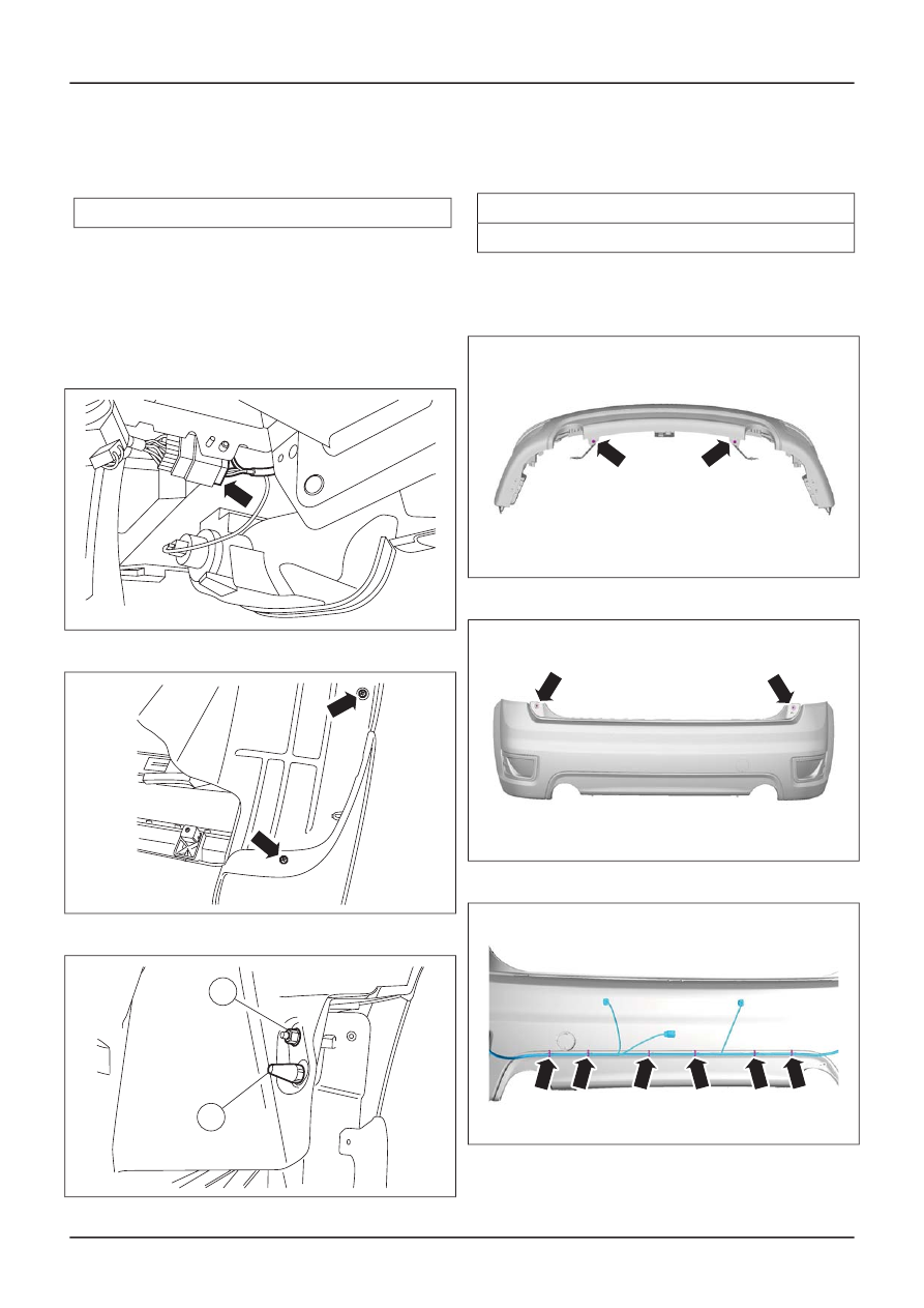
Removal
NOTE: Removal steps in this procedure may
contain installation details.
1.
E50608
2.
TIE39853
3.
TIE39855
1
2
4.
E65196
5.
E65197
6.
E65198
G545207en
501-19-
9
Bumpers
501-19-
9
REMOVAL AND INSTALLATION