Ford Focus RS (2011 year). Instruction - part 67


  Index      Ford     Ford Focus RS - service repair manual (2011 year) in english


Search            


Content   ..  65  66  67  68   ..


Ford Focus RS (2011 year). Instruction - part 67


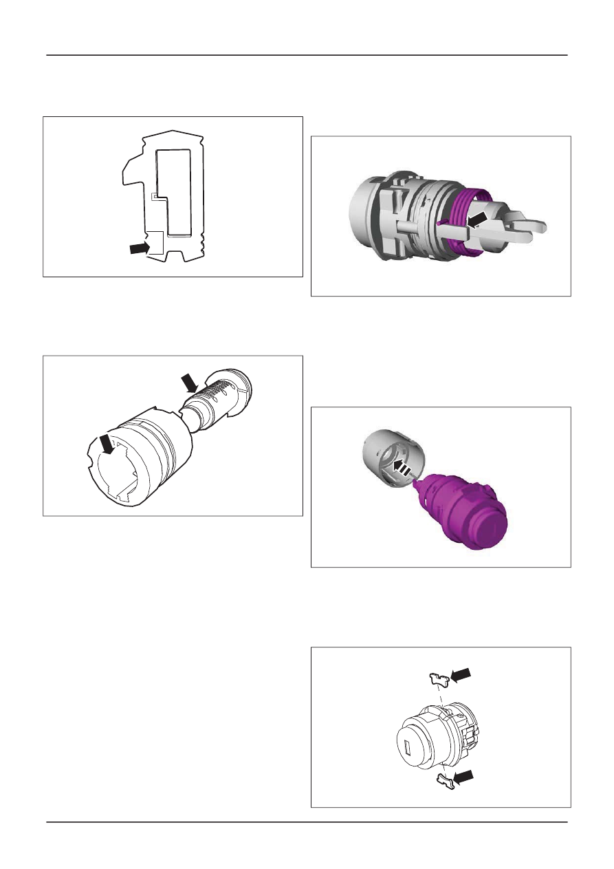
Assemble the hood lock cylinder barrel
tumblers in the correct order.

E43309

Item 11

Hood lock cylinder barrel cover

NOTE: Make sure that the hood lock cylinder cover
guide indents align with the hood lock cylinder
barrel.

E43467

Item 7

Hood lock cylinder connecting clip

NOTE: An audible click can be heard when the
hood lock cylinder return spring cap is installed
correctly.

Item 6

Hood lock cylinder return spring

1. Install the hood lock cylinder return spring

in the same position as removed.

E59904

Item 5

Hood lock cylinder barrel cover

1. NOTE: The hood lock cylinder can only be

installed to the hood lock cylinder housing
in one position.

Install the hood lock cylinder barrel cover
into the hood lock cylinder housing.

E60448

Item 4

Hood lock cylinder barrel cover locking

clips

1. Install the hood lock cylinder barrel cover

locking clips.

E43522

G413491en

501-14-

215

Handles, Locks, Latches and Entry Systems

501-14-

215

DISASSEMBLY AND ASSEMBLY

Item 2

Hood lock cylinder locking pin

1. Using a suitable

Punch

, install the hood lock

cylinder locking pin.

E43523

Item 1

Hood lock cylinder locking pins

1. Using a suitable

Punch,

install the hood lock

cylinder locking pins.

E43524

G413491en

501-14-

216

Handles, Locks, Latches and Entry Systems

501-14-

216

DISASSEMBLY AND ASSEMBLY

Ignition Lock Cylinder — Vehicles With: Keyless Vehicle System

Disassembly

1.

Refer to: Ignition Lock Cylinder - Vehicles With:

Keyless Vehicle System

(501-14 Handles,

Locks, Latches and Entry Systems, Removal
and Installation).

2.

E115229

3.

E115227

4.

1

2

E115230

5.

E115228

6. NOTE: Make sure to read the key code from

the key entry to the end of the lock barrel in
sequence.

NOTE: Make a note of the position and
orientation of the ignition lock cylinder barrel
tumblers.

NOTE: One group of tumblers is signed with a
one digit number (1 to 5), the other group of
tumblers is signed with a two digit number (11
to 15).

G1187730en

501-14-

217

Handles, Locks, Latches and Entry Systems

501-14-

217

DISASSEMBLY AND ASSEMBLY

E115740

x10

x10

Assembly

7.

E115898

8.

E115900

9. NOTE: One group of tumblers is signed with a

one digit number (1 to 5), the other group of

G1187730en

501-14-

218

Handles, Locks, Latches and Entry Systems

501-14-

218

DISASSEMBLY AND ASSEMBLY

tumblers is signed with a two digit number (11
to 15).

E70124

x10

x10

10.

E115894

11.

E115906

12.

E115909

13.

E115226

14.

E115746

G1187730en

501-14-

219

Handles, Locks, Latches and Entry Systems

501-14-

219

DISASSEMBLY AND ASSEMBLY

15.

E115751

16.

E115902

17.

E115905

G1187730en

501-14-

220

Handles, Locks, Latches and Entry Systems

501-14-

220

DISASSEMBLY AND ASSEMBLY

Ignition Lock Cylinder — Vehicles Without: Keyless Vehicle System

General Equipment

Flat-bladed screwdriver

1. Remove the ignition lock cylinder.

For additional information,

refer to: Ignition

Lock Cylinder - Vehicles Without: Keyless

Vehicle System

(501-14 Handles, Locks,

Latches and Entry Systems, Removal and
Installation).

2. Disassemble the components in the order

indicated in the following illustration(s) and
table(s).

4

5

6

7

9

2

7

8

8

E43468

3

1

G328436en

501-14-

221

Handles, Locks, Latches and Entry Systems

501-14-

221

DISASSEMBLY AND ASSEMBLY

Description

Item

Ignition lock cylinder locking button

See Disassembly Detail
See Assembly Detail

1

Ignition lock cylinder housing

See Disassembly Detail
See Assembly Detail

2

Ignition lock cylinder retaining clip

See Assembly Detail

3

Ignition lock cylinder barrel cover

4

Ignition lock cylinder retaining clip

See Disassembly Detail
See Assembly Detail

5

Ignition lock cylinder barrel guide

See Assembly Detail

6

Description

Item

Ignition lock cylinder barrel tumblers

See Disassembly Detail
See Assembly Detail

7

Ignition lock cylinder barrel tumbler springs

8

Ignition lock cylinder barrel

9

3. To assemble, reverse the disassembly

procedure.

4. Install the ignition lock cylinder.

For additional information,

refer to: Ignition

Lock Cylinder - Vehicles Without: Keyless
Vehicle System

(501-14 Handles, Locks,

Latches and Entry Systems, Removal and
Installation).

Disassembly Details

Item 1

Ignition lock cylinder locking button

E62270

1

2

1. Remove the ignition lock cylinder locking

button.

1. Using a suitable tool, release the ignition lock

cylinder locking button leaf spring and
remove the ignition lock cylinder locking
button leaf spring.

2. Detach the ignition lock cylinder locking

button from the ignition lock cylinder housing
and remove the ignition lock cylinder locking
button.

Item 2

Ignition lock cylinder housing

1. Remove the ignition lock cylinder housing.

1. Operate the ignition lock cylinder retaining

clip.

2. Slide the ignition lock cylinder housing away

from the ignition lock cylinder barrel guide.

1

2

E43472

Item 5

Ignition lock cylinder retaining clip

1. Using a suitable

Flat-bladed screwdriver

remove the

ignition lock cylinder retaining

clip.

E43471

G328436en

501-14-

222

Handles, Locks, Latches and Entry Systems

501-14-

222

DISASSEMBLY AND ASSEMBLY


Content   ..  65  66  67  68   ..