Ford Focus RS (2011 year). Instruction - part 4


  Index      Ford     Ford Focus RS - service repair manual (2011 year) in english


Search            


Content   ..  2  3  4  5   ..


Ford Focus RS (2011 year). Instruction - part 4


Install new door hinge center retaining bolts.

TIE0037619

15 Nm

14. Close the door.

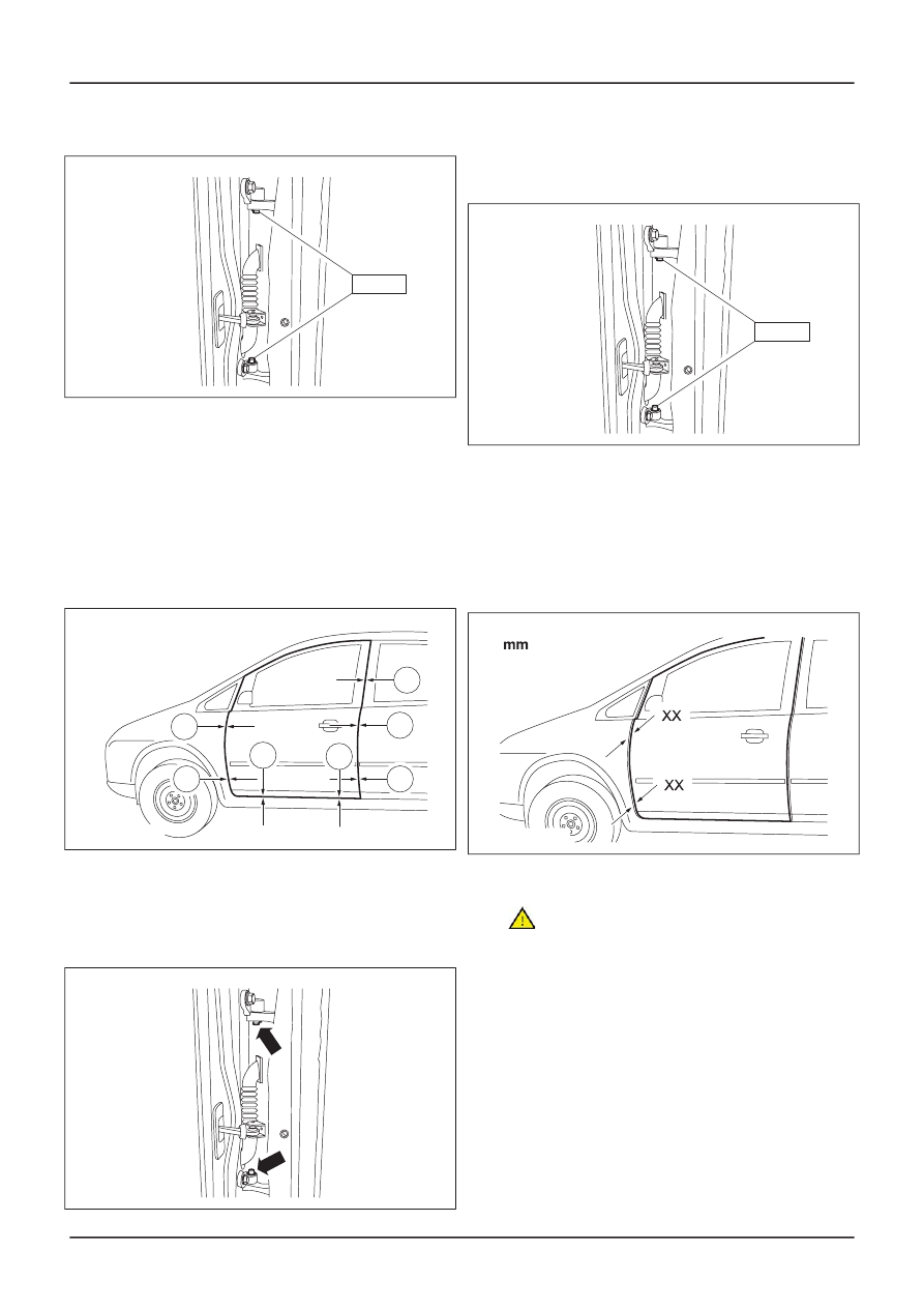
15. NOTE: Make sure that the door is in the

fully closed position.

Check and note any misalignment of the door
in relation to the door frame.

1. 3.5 mm ± 1.0 mm.
2. 6.0 mm ± 2.0 mm.
3. 4.5 mm ± 1.5 mm.

TIE0037259

1

1

3

1

1

2

2

16. If further adjustment is required repeat the

door hinge to A-pillar adjustment.

17. If no further adjustment is required, remove

the door hinge center retaining bolts.

TIE0037618

18. Apply a coating of

adhesive

to the door

hinge center retaining bolts.

19. Install the door hinge center retaining bolts.

TIE0037619

15 Nm

20. Close the door.

21. NOTE: Make sure that the door is in the

fully closed position.

Check and note any misalignment of the door
in relation to the fender.

• XX = -1.0 mm +1.0 mm to -2.0 mm.

TIE0037260

22. Open the door.

23.

CAUTION: Protect the door using a soft

cloth to prevent damage.

G393925en

501-03-

11

Body Closures

501-03-

11

GENERAL PROCEDURES

With the aid of another technician and a
suitable

transmission jack

, support the door.

TIE41214

24. Loosen the door hinge to door retaining

screws one complete turn.

TIE0037257

25.

CAUTION: Make sure that the door hinge

cones are correctly located and have a
common pivot center line.

Adjust the door hinges as necessary.

TIE0037255

26.

CAUTION: Make sure that the door hinge

cones are correctly located and have a
common pivot center line.

Tighten the door hinge to door retaining
screws.

TIE0037262

48 Nm

27. Close the door.

28. NOTE: Make sure that the door is in the

fully closed position.

Check and note any misalignment of the door
in relation to the fender.

G393925en

501-03-

12

Body Closures

501-03-

12

GENERAL PROCEDURES

• XX = -1.0 mm +1.0 mm to -2.0 mm.

TIE0037260

29. If further adjustment is required repeat the

door hinge to door adjustment.

30. NOTE: Make sure that the door is in the

fully closed position.

If no further adjustment is required check
and note any misalignment of the door in
relation to the body side panel.

• XX = 0.0 mm +1.0 mm to -0.0 mm.

TIE0037261

31. Open the door and mark the position of the

door latch striker plate, to use as reference
points as necessary.

32. Loosen the striker plate retaining screws

one half turn.

TIE0037256

33.

CAUTION: Protect the B-pillar using a

soft cloth to prevent damage.

Using a suitable soft faced hammer, adjust
the striker plate as necessary.

TIE0037616

34. Tighten the striker plate retaining screws.

TIE0037264

20 Nm

35. Close the door.

36. NOTE: Make sure that the door is in the

fully closed position.

Check and note any misalignment of the door
in relation to the body side panel.

• XX = 0.0 mm +1.0 mm to -0.0 mm.

TIE0037261

G393925en

501-03-

13

Body Closures

501-03-

13

GENERAL PROCEDURES

37. If further adjustment is required repeat the

door latch striker plate to B-pillar
adjustment.

38. If no further adjustment is required open

the door.

39. Connect the electrical connector.

TIE41216

40. Attach the electrical connector to the

A-pillar.

TIE41215

41.

CAUTION: Make sure that the door

check strap is correctly aligned.

Attach the door check strap to the A-pillar.

1. Pull the check strap to the open position.
2. Install the retaining screw.

TIE0037263

1

23 Nm

2

G393925en

501-03-

14

Body Closures

501-03-

14

GENERAL PROCEDURES

Front Door Alignment — 4-Door/5-Door/Wagon

General Equipment

Transmission jack

Materials

Specification

Name

WSK-M2G349-A7

Adhesive - Loctite 243

NOTE: The rear door alignment must be carried
out before carrying out front door alignment.

For additional information,

refer to: Rear Door

Alignment

(501-03 Body Closures, General

Procedures).

1. NOTE: Make sure that the front and rear

doors are in the fully closed position.

Check and note any misalignment of the
front door in relation to the door frame and
the front edge of the rear door.

1. 3.5 mm ± 1.0 mm.
2. 6.0 mm ± 2.0 mm.
3. 4.5 mm ± 1.5 mm.

TIE0037259

1

1

3

1

1

2

2

2. If adjustment is required open the front door

and mark the position of the front door
hinges, to use as reference points as
necessary.

3. NOTE: Due to limited access to the front door

hinge retaining screws on the A-pillar, the
front door must be removed.

Detach the door check strap from the
A-pillar.

1. Remove the retaining screw.

2. Push the check strap to the fully closed

position.

TIE0037258

1

2

4. Detach the electrical connector from the

A-pillar.

TIE41215

5. Disconnect the electrical connector.

TIE41216

6.

CAUTION: Protect the door using a soft

cloth to prevent damage.

G391258en

501-03-

15

Body Closures

501-03-

15

GENERAL PROCEDURES

With the aid of another technician and a

suitable transmission jack, support the door.

TIE41214

7. Remove and discard the door hinge center

retaining bolts.

TIE0037618

8.

CAUTION: Take care when moving the

door upwards as considerable force may be
required to separate the door hinges from
the door hinge cones.

With the aid of another technician remove
the front door.

9. Loosen the door hinge to A-pillar retaining

screws one half turn.

TIE0037625

10.

CAUTION: Make sure that the door

hinges maintain a common pivot center
line.

Adjust the door hinges as necessary.

TIE0037627

11.

CAUTION: Make sure that the door

hinges maintain a common pivot center
line.

Tighten the door hinge to A-pillar retaining
screws.

E0037626

30 Nm

30 Nm

12. Install the front door.

• Make sure that the door hinge cones are

correctly located.

13. NOTE: Do not apply adhesive at this stage.

G391258en

501-03-

16

Body Closures

501-03-

16

GENERAL PROCEDURES

Install new door hinge center retaining bolts.

TIE0037619

15 Nm

14. Close the front door.

15. NOTE: Make sure that the front and rear

doors are in the fully closed position.

Check and note any misalignment of the
front door in relation to the door frame and
the front edge of the rear door.

1. 3.5 mm ± 1.0 mm.
2. 6.0 mm ± 2.0 mm.
3. 4.5 mm ± 1.5 mm.

TIE0037259

1

1

3

1

1

2

2

16. If further adjustment is required repeat the

door hinge to A-pillar adjustment.

17. If no further adjustment is required, remove

the door hinge center retaining bolts.

TIE0037618

18. Apply a coating of

adhesive

to the door

hinge center retaining bolts.

19. Install the door hinge center retaining bolts.

TIE0037619

15 Nm

20. Close the front door.

21. NOTE: Make sure that the front door is in

the fully closed position.

Check and note any misalignment of the
front door in relation to the fender.

• XX = -1.0 mm +1.0 mm to -2.0 mm.

TIE0037260

22. Open the front door.

G391258en

501-03-

17

Body Closures

501-03-

17

GENERAL PROCEDURES

23.

CAUTION: Protect the door using a soft

cloth to prevent damage.

With the aid of another technician and a
suitable

transmission

jack

, support the door.

TIE41214

24. Loosen the door hinge to door retaining

screws one complete turn.

TIE0037257

25.

CAUTION: Make sure that the door hinge

cones are correctly located and have a
common pivot center line.

Adjust the door hinges as necessary.

TIE0037255

26.

CAUTION: Make sure that the door hinge

cones are correctly located and have a
common pivot center line.

Tighten the door hinge to door retaining
screws.

TIE0037262

48 Nm

27. Close the front door.

28. NOTE: Make sure that the front door is in

the fully closed position.

Check and note any misalignment of the
front door in relation to the fender.

G391258en

501-03-

18

Body Closures

501-03-

18

GENERAL PROCEDURES


Content   ..  2  3  4  5   ..