Fiat Qubo (2018 year). Manual - part 7


  Index      Fiat     Fiat Qubo (2018 year) - manual in english


Search            


Content      ..     5      6      7      8     ..


Fiat Qubo (2018 year). Manual - part 7


switch off the engine and pull the

handbrake;

engage first gear or reverse;

wear the reflective safety jacket

(compulsory by law in certain countries)
before getting out of the vehicle;

indicate that the vehicle has broken

down using the devices required by
the law in the current country (e.g.
warning triangle, hazard lights, etc.);

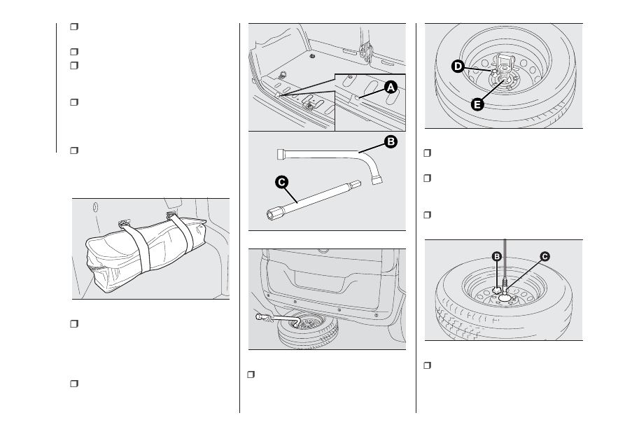
open the tailgate, take the tool bag

fig. 111 located on the left of the boot
by releasing the elastic straps and take
to the wheel to be replaced;

take wheel spanner B fig. 112 and

the extension with pentagonal fitting C;
inside the load area, fit extension C
on bolt A; use spanner B to lower the
wheel by unwinding the wire;

use the spanner B to remove the

wheel from the vehicle fig. 113;

unscrew knob D fig. 114 and release

the rim from bracket E, removing it
from the hole of the rim;

for vehicles with alloy rims, remove

the hub cap;

loosen the fixing bolts of the wheel

to be replaced by about one turn, using
the spanner provided;

for wheels with steel rims, remove

the wheel cap;

turn the jack to open it partially and

then position it under the vehicle at
the references A fig. 116 near the wheel
to be replaced;

111

F0T0206

112

F0T0922

113

F0T0419

114

F0T0923

115

F0T0169

104

IN

AN

EMERGENCY

-------------------------------------------------------------------------------------------------------------------------------------------------------------

turn the jack to open it until the

groove A fig. 117 of the jack is correctly
inserted in the lower profile B on the
side member;

warn anybody nearby that the

vehicle is about to be lifted. They must
stay clear and not touch the vehicle
until it is back on the ground;

operate the jack and lift the vehicle

until the wheel is several centimetres off
the ground.

When turning the crank, ensure that it
rotates freely in order to avoid grazing
your hands against the ground. The
moving components of the jack (screws
and joints) can also cause injuries:
avoid touching them. If you come into
contact with lubricating grease, clean
yourself thoroughly;

fully loosen the four fastening bolts

and remove the wheel;

make sure the contact surfaces

between spare wheel and hub are
clean so that the fastening bolts will not
come loose;

fit the standard wheel by inserting

the first bolt two threads B fig. 118 into
the hole nearest to the inflation valve
A;

fit the hub cap, making sure that the

symbol

(on the cup) aligns with the

inflation valve, and then insert the other
three bolts;

tighten the bolts using the spanner

provided;

for cars with alloy rim, fit the hub

cap;

turn the jack handle to lower the

vehicle, and remove the jack;

use the wrench provided to fasten

the bolts completely in a criss-cross
fashion as shown in fig. 119.

At the end of the operation

fix bracket A fig. 120 to the wheel

after passing it through the hole, insert
the threaded pin into one of the bolt
holes and secure by tightening knob B;

for vehicles with allow wheels,

remove the adapter D fig. 121 and
introduce the bracket into the adapter
D, insert the pin into the hole and
secure with the knob F;

116

F0T0125

117

F0T0126

118

F0T0282

119

F0T0128

105

-------------------------------------------------------------------------------------------------------------------------------------------------------------

position the wheel vertically and rest

the fitted adaptor on the inside of the
rim, then using the screws provided fix
the wheel to the adaptor fig. 122.
Tighten the screws with the wheel
spanner;

check replaced wheel positioning

under the floor (the lifting system is
supplied with a clutch to limit the end of
the stroke). Incorrect positioning may
jeopardise safety;

lift the wheel by fastening the bolt A

fig. 112;

put jack and tools back in the

specific tool bag;

reposition the tool bag in the boot;

secure the tool box to the hooks.

WARNING

104) If left in the passenger compartment,
the punctured wheel and jack constitute
a serious risk to the safety of occupants in
the event of accidents or sharp braking.
Therefore, always place both the jack and
punctured wheel in the dedicated housing.
105) It is extremely dangerous to attempt
to change a wheel on the side of the
vehicle next to the driving lane: make sure
that the vehicle is at a sufficient distance
from the road, to avoid being run over.

106) The spare wheel (for versions/
markets, where provided) is specifically for
your vehicle. Therefore, it must not be
used on other models. Do not use spare
wheels of other models on your vehicle.
The spare wheel must be used only in an
emergency. Use of the spare wheel must
be strictly reduced to the necessary
minimum.
107) Use your hazard lights, warning
triangle, etc to show that your vehicle is
stationary. Passengers should get out
of the vehicle, particularly if it is heavily
loaded, and wait for the wheel to be
changed away from the traffic. If you are on
a slope or uneven surface, place wedges
or other suitable objects under the wheels
to secure the vehicle. Have the wheel
repaired and refitted as soon as possible.
Do not apply grease to the bolt threads
before fitting: they could come unscrewed.
108) The jack is a tool developed and
designed only for changing a wheel, if a
tyre gets punctured or damaged, on the
vehicle with which it is supplied or on other
vehicles of the same model. Any other
use, e.g. to jack up other vehicle models or
different things, is strictly prohibited. Never
use it to carry out maintenance or repairs
under the vehicle or to change summer/
winter wheels and vice versa: we advise
you to contact a Fiat Dealership. Never go
under the raised vehicle: use it only in
the positions indicated. Do not use the jack
for loads higher than the one shown on
its label.

120

F0T0924

121

F0T0925

122

F0T0926

106

IN

AN

EMERGENCY

-------------------------------------------------------------------------------------------------------------------------------------------------------------

Never start the engine with vehicle raised. If
the vehicle is raised more than necessary,
everything can become more unstable,
with the risk of the vehicle dropping
violently. Thus, lift the vehicle only as
needed in order to access the spare wheel.
109) Incorrect hub cap assembly may
cause it to come off when the vehicle is
moving. Never tamper with the inflation
valve. Never introduce tools of any kind
between rim and tyre. Check tyre and
space-saver wheel pressures regularly,
referring to the values shown in the
"Technical data" chapter.
110) Never use the space-saver spare
wheel for more than strictly necessary and
never exceed 80 km/h. On the space-saver
wheel there is an orange label,
summarising the main warnings regarding
usage restrictions. Never remove or cover
the label. Important! For temporary use
only! 80 km/h max.! Replace with standard
wheel as soon as possible.

WARNING

34) When turning the jack handle make
sure that it can turn freely without scraping
your hand against the ground. The moving
components of the jack ("worm screw"
and joints) can also cause injuries: do not
touch them. If you come into contact
with lubricating grease, clean yourself
thoroughly.
35) Contact a Fiat Dealership as soon as
possible to have the correct tightening
of the fixing bolts checked.

FIX & GO
AUTOMATIC KIT

111) 112)

36)

The Fix&Go automatic quick tyre repair
kit is located in a special container in
the boot.
The quick tyre repair kit contains fig.
123:

one cartridge A containing sealant

and fitted with: transparent tube for
injecting the sealant D and sticker
C with the wording “Max 80 km/h” to
be placed in a clearly visible position
(e.g. on the dashboard) after repairing
the tyre;

one compressor B;

one leaflet containing instructions for

using the kit;

a pair of gloves located in the hose

compartment of the cartridge D.

TYRE REPAIRING AND
PRESSURE RESTORING
PROCEDURE

Proceed as follows:

stop the vehicle in a position that is

not dangerous for oncoming traffic
where you can carry out the procedure
safely. The ground must be flat and
sufficiently compact;

stop the engine, engage the hazard

warning lights and the parking brake;

wear the reflective safety jacket

before getting out of the vehicle
(anyway comply with the laws in force
in the country you are driving in);

insert the cartridge A containing the

sealant in the proper compartment of
the compressor B, pressing it down
hard fig. 123. Remove the adhesive
speed label C and apply it in a visible
position fig. 124;

wear the gloves;

A

C

B

D

123

F0T0931

107

-------------------------------------------------------------------------------------------------------------------------------------------------------------

remove the cap from the tyre valve

and connect and screw the transparent
tube of the sealing fluid D fig. 123
onto the valve. If a 250 ml cartridge is
present the housing of the transparent
tube is provided with removable ring
to facilitate extraction. Make sure that
the ON-OFF button E fig. 125 is in
the off position (button not pressed);

plug the electric connector F fig. 126

into the 12V socket of the vehicle and
start the vehicle engine;

operate the compressor by pressing

the ON-OFF button E fig. 125. When
the pressure shown in the Owner
Handbook or on the specific label
appears on the pressure gauge G, stop
the compressor by pressing the
ON-OFF button E again;

disconnect the cartridge A from the

compressor, by pressing the release
button H and lifting the cartridge A
upwards fig. 127.

If the pressure gauge G fig. 125
indicates a pressure lower than 1.8 bar
/ 26 psi 15 minutes after starting the
compressor, switch off the compressor,
disconnect the sealing fluid tube D
from the tyre valve and remove the
cartridge A from the compressor fig.
127.
Move the vehicle by approximately 10
m to promote the distribution of
sealant; stop the vehicle safely, operate
the handbrake and restore pressure
using the black inflation pipe L fig. 128
to reach the required pressure. If also
in this case, the pressure is lower
than 1.8 bar / 26 psi 15 minutes after
turning on, do not resume driving
but contact a Fiat Dealership.

8 km / 5 mi

124

F0T0932

E

M

G

125

F0T0933

126

F0T0934

A

H

127

F0T0935

128

F0T0936

108

IN

AN

EMERGENCY

-------------------------------------------------------------------------------------------------------------------------------------------------------------

After driving for about 8 km / 5 miles,
position the vehicle in a safe and
suitable area and engage the
handbrake. Take the compressor and
restore pressure using the black
inflation tube L fig. 128.
If the pressure shown is higher than 1.8
bar / 26 psi, restore the pressure and
drive safely to a Fiat Dealership as soon
as possible. If, however, the pressure
is lower than 1.8 bar / 26 psi, do not
resume driving but contact a Fiat
Dealership.

INFLATION PROCEDURE

Proceed as follows:

stop the vehicle safely, as shown

above, and operate the handbrake;

extract the black inflation tube L fig.

128 and screw it firmly onto the tyre
valve. Follow the instructions shown in
fig. 126 and fig. 128.
Press the air release button M fig. 125
to adjust any tyre overpressure.

CARTRIDGE
REPLACEMENT

Proceed as follows:

only use original Fix&Go cartridges,

which can be purchased from the
Fiat Dealership.

to remove the cartridge A fig. 123

press the release button H fig. 127 and
lift it.

WARNING

111) The information required by the
applicable regulation is indicated on the
Fix&Go kit package label. Carefully read
the label on the cartridge before use, avoid
improper use. The kit should be used by
adults and cannot be used by children.
112) IMPORTANT: Do not exceed 80 km/h.
Avoid sudden acceleration or braking.
The kit provides a temporary repair,
therefore the tyre must be examined and
repaired by a specialist as soon as
possible. Before using the kit, ensure that
the tyre is not excessively damaged and
that the rim is in good condition, otherwise
do not use it and call roadside assistance.
Do not remove foreign bodies from the
tyre. Do not let the compressor turned on
for more than 20 consecutive minutes -
overheating hazard.

WARNING

36) The sealant fluid is effective with
external temperatures between -40°C and
+55°C. The sealant has an expiry date. It
is possible to repair tyres which have been
damaged on tread up to a diameter of 6
mm. Show the cartridge and the label
to the personnel who will handle the tyre
treated with the tyre repair kit

CHANGING A BULB

GENERAL
INSTRUCTIONS

113) 114) 115) 116) 117)

Before replacing a bulb check the

contacts for oxidation;

burnt bulbs must be replaced by

others of the same type and power;

always check the headlight beam

direction after changing a bulb;

when a light is not working, check

that the corresponding fuse is intact
before replacing a bulb. For the location
of fuses, refer to the paragraph
"Replacing fuses" in this chapter.

IMPORTANT A slight misting may
appear on the internal surface of the
headlight: this does not indicate a fault
and is caused by low temperature
and the degree of humidity in the air.
Misting will rapidly disappear when the
headlights are switched on. The
presence of drops inside the headlights
indicates infiltration of water. Contact
a Fiat Dealership.

109

-------------------------------------------------------------------------------------------------------------------------------------------------------------

WARNING

113) Modifications or repairs to the electric
system that are not carried out properly
or do not take the system technical
specifications into account can cause
malfunctions leading to the risk of fire.
114) Halogen bulbs contain pressurised
gas, in the case of breakage they may
burst causing glass fragments to be
projected outwards.
115) Halogen bulbs must be handled
holding the metal part only. Touching the
transparent part of the bulb with your
fingers may reduce the intensity of the
emitted light and even reduce the lifespan
of the bulb. In the event of accidental
contact, wipe the bulb with a cloth
moistened with alcohol and let the bulb dry.
116) Where possible, it is advisable to
have bulbs changed at a Fiat Dealership.
The correct operation and direction of
the external lights are absolutely essential
for the safety of the car and of compliance
with the law.
117) Replace the bulbs with the engine
stopped and in a position in which it is not
danger for oncoming traffic and where
you perform the replacement safely (see
the “When parked” paragraph). Also ensure
that the engine is cold, to prevent the risk
of burns.

110

IN

AN

EMERGENCY

-------------------------------------------------------------------------------------------------------------------------------------------------------------

BULBS TYPES

Various types of bulbs are fitted to your vehicle.

All-glass bulb: (type A) these are pressure fitted - pull to remove.

Bayonet bulb: (type B) to remove them press the bulb and turn it
anticlockwise.

Cylindrical bulbs: (type C) release them from their contacts to remove.

Halogen bulbs: (type D) to remove the bulb, release the clip holding
the bulb in place.

Halogen bulbs: (type E) to remove the bulb, release the clip holding
the bulb in place.

Xenon gas discharge bulbs: (type F) for replacement, contact a Fiat
Dealership.

.

111

-------------------------------------------------------------------------------------------------------------------------------------------------------------

Light bulbs

Light bulbs

Type

Power

Figure ref.

Main beam headlights

H4

55W

E

Dipped headlights

H4

60W

D

Front side lights

W5W

5W

A

Front direction indicators

PY21W

2IW

B

Side turn light

WY5W

5W

A

Rear direction indicators

PY2IW

21W

B

Tail lights/rear fog lights

P4/21W

4W/21W

B

Stop

P21W

21W

B

Number plate

W5W

5W

C

3rd brake light

(*)

W5W

5W

A

Reversing light

P21W

21W

B

Front fog lights (for versions/markets where provided)

H1

55W

E

Front roof light with movable lens

C

10W

C

Front ceiling light with spot lights (for versions/
markets, where provided)

C

10W

C

Rear roof light (for versions/markets, where provided)

C

10W

C

(*)IMPORTANT For versions/markets, where provided, in the versions with tinted windows replace the whole light unit, as it is sealed.

112

IN

AN

EMERGENCY

-------------------------------------------------------------------------------------------------------------------------------------------------------------

REPLACING AN
EXTERIOR BULB

For the type of bulb and relevant power
rating, see “Changing a bulb”.

FRONT LIGHT CLUSTERS

The front light clusters fig. 129 contain
sidelight, dipped beam, main beam and
direction indicator bulbs.
The bulbs are arranged inside the light
cluster as follows:

A Side lights/tail lights and

main/dipped beam headlights;

B Direction indicators.

SIDE LIGHTS

To replace the bulb, proceed as follows:

remove the protective cover A fig.

129;

turn the bulb holder A fig. 130

anticlockwise and remove it;

remove the bulb B and replace it;

refit the new bulb, insert the bulb

holder A fig. 130 again and then refit
the protective lid A fig. 129 correctly.

DIPPED/MAIN BEAM
HEADLIGHTS

To change the bulb (double filament),
proceed as follows:

remove the protective cover A fig.

129;

release the bulb holder clip;

remove the bulb A fig. 131 from

connector B and replace it;

refit the new bulb by inserting it on

connector B and then make the
contour of the metallic part mate with
the grooves obtained on the headlight
parabola;

refit the bulb holder clip and refit the

protective lid A fig. 129 correctly.

129

F0T0093

130

F0T0094

131

F0T0095

113

-------------------------------------------------------------------------------------------------------------------------------------------------------------

DIRECTION INDICATORS

Front

To replace the bulb, proceed as follows:

turn the protective lid B fig. 129

anticlockwise;

extract the bulb A fig. 132 and

replace it;

refit the protective lid B correctly.

Side

To replace the bulb, proceed as follows:

adjust the lens A fig. 133 to

compress in the internal catch B fig.
134, then pull the cluster outwards;

turn the bulb holder C anticlockwise,

extract the press-fitted bulb D and
replace it;

refit the bulb holder C in the lens and

turn it clockwise;

refit the cluster making sure that the

internal catch B clips into position.

FOG LIGHTS
(for versions/markets, where provided)

IMPORTANT Contact Fiat Dealership to
replace the front fog lights.

REAR LIGHT CLUSTERS

The rear light clusters contain the bulbs
for the side lights, direction indicators
and reversing/rear fog and brake lights.

To access the light clusters, proceed
as follows:

open the rear swing doors;

loosen the screws A fig. 135 so as

to access the light cluster B fig. 136;

remove the connector C fig. 136.

The bulbs are arranged inside the light
cluster fig. 137 and fig. 138 as follows:

Brake lights

Direction indicators

Reverse lights

132

F0T0096

133

F0T0097

134

F0T0098

135

F0T0099

114

IN

AN

EMERGENCY

-------------------------------------------------------------------------------------------------------------------------------------------------------------

Side lights/rear fog light

Pull the 5 tabs E fig. 137 outwards to
access the bulbs.

THIRD BRAKE LIGHTS

Tailgate versions

To replace the bulbs, proceed as
follows fig. 139 - fig. 140:

open the tailgate and loosen the two

retaining screws A;

disconnect the electrical connector

B;

release the retainer tab C and open

the bulb holder assembly;

extract the snap-fitted bulb and

replace it.

136

F0T0100

138

F0T0102

137

F0T0101

139

F0T0212

A

C

A

B

140

F0T0443

115

-------------------------------------------------------------------------------------------------------------------------------------------------------------

NUMBER PLATE LIGHTS

Proceed as follows to replace the bulbs
A fig. 141:

operate the holding tabs at the

points indicated by the arrows, and
remove the bulb holder;

turn the bulb holder B fig. 142

anticlockwise, then remove bulb C.

REPLACING AN
INTERIOR BULB

For the type of bulb and relevant power
rating, see “Changing a bulb”.

FRONT CEILING LIGHT

Roof light with movable lens
To replace the bulbs, proceed as
follows:

extract the ceiling light A fig. 143 by

operating in the points shown by the
arrows;

open the lid B fig. 144 as shown;

remove bulb C fig. 144 by releasing

it from the side contacts, then insert the
new bulb and make sure it is correctly
clamped between these contacts;

close the lid and secure the ceiling

light into its housing, making sure it
locks properly into place.

Front ceiling light with map reading
lights

(for versions/markets, where provided)

To replace the bulbs, proceed as
follows:

operate in the points indicated by

the arrows and remove light A fig. 145;

open protective flap B fig. 146;

replace the bulbs C releasing them

from the side contacts making sure that
the new bulbs are correctly secured
between the contacts;

re-close the lid B fig. 146 and secure

light A fig. 145 into its housing locking
it properly.

141

F0T0104

142

F0T0105

143

F0T0106

144

F0T0458

116

IN

AN

EMERGENCY

-------------------------------------------------------------------------------------------------------------------------------------------------------------

REAR CEILING LIGHT

To replace the bulb, proceed as follows:

remove roof light A fig. 147 working

at the points indicated by the arrows;

open the lid B fig. 148 as shown;

remove bulb C fig. 148 by releasing

it from the side contacts, then insert the
new bulb and make sure it is correctly
clamped between these contacts;

close the lid B and secure the ceiling

light into its housing, making sure it
locks properly into place.

REMOVABLE CEILING
LIGHT
(for versions/markets, where provided)

To replace the bulb, proceed as follows:

press button A fig. 149 and extract

the removable ceiling light B;

extract the ceiling light by operating

in the points shown by the arrows;

change the bulb C fig. 150 by

releasing it from the side contacts and
making sure the new bulb is correctly
fastened between these contacts.

145

F0T0143

146

F0T0144

147

F0T0107

148

F0T0458

AUTO

149

F0T0108

AUTO

150

F0T0109

117

-------------------------------------------------------------------------------------------------------------------------------------------------------------

LUGGAGE
COMPARTMENT LIGHT

To change the bulb, proceed as follows:

open the tailgate;

remove the light A fig. 151 levering in

the point shown by the arrow;

open the protection B and replace

the snap-fitted bulb;

close the cover B on the lens;

refit the roof light A by inserting it in

its correct position firstly on one side
and then pressing on the other until
it clicks into place.

REPLACING FUSES

GENERAL INFORMATION

118) 119) 120) 121) 122)

37)

Fuses protect the electrical system:
they intervene (blow) in the event of a
failure or improper action on the
system.
When a device does not work, check
the condition of its protection fuse: the
filament A fig. 152 must be intact.
If it is not, replace the blown fuse with
another with the same amperage (same
colour).
B intact fuse.
C fuse with damaged filament.
To change a fuse, use the tongs D
located in the tool bag or the Fix & Go
container (for versions/markets, where
provided).

Refer to the tables on the following
pages to identify the protective fuse.

ENGINE BAY FUSE BOX

The fuse box is on the right-hand side
of the engine.

Removing the fuse box lid

Proceed as follows:

remove protective cover A fig. 153

from the positive battery terminal by
lifting it upwards;

press the tab A fig. 154 and remove

the fuse box protective cover B;

151

F0T0251

152

F0T0015

153

F0T0171

154

F0T0172

118

IN

AN

EMERGENCY

-------------------------------------------------------------------------------------------------------------------------------------------------------------

move the cover towards the

headlight, turning it anticlockwise (as
shown by the arrow) and then remove it
fig. 155;

the fuse box can be accessed in this

manner fig. 157.

38)

Refitting the fuse box lid

Proceed as follows to refit the lid:

insert the two tabs A fig. 156 in the

respective seats located on the fuse
box;

refasten the tab B in the

corresponding seat until it clicks.

155

F0T0173

156

F0T0174

119

-------------------------------------------------------------------------------------------------------------------------------------------------------------


Content      ..     5      6      7      8     ..