Fiat 500L Living (2019 year). Manual - part 8


  Index      Fiat     Fiat 500L Living (2019 year) - manual in english


Search            


Content      ..     6      7      8      9     ..


Fiat 500L Living (2019 year). Manual - part 8


release the bulb and replace it;

reinsert the bulb/bulb holder unit B

by turning it clockwise;

reconnect the electrical connection

A;

refit the flap and check that it is

correctly locked.
If the flap is not present, access the
bulb holder through the lower part
of the rear bumper fig. 103 to replace
the reversing and rear fog light.
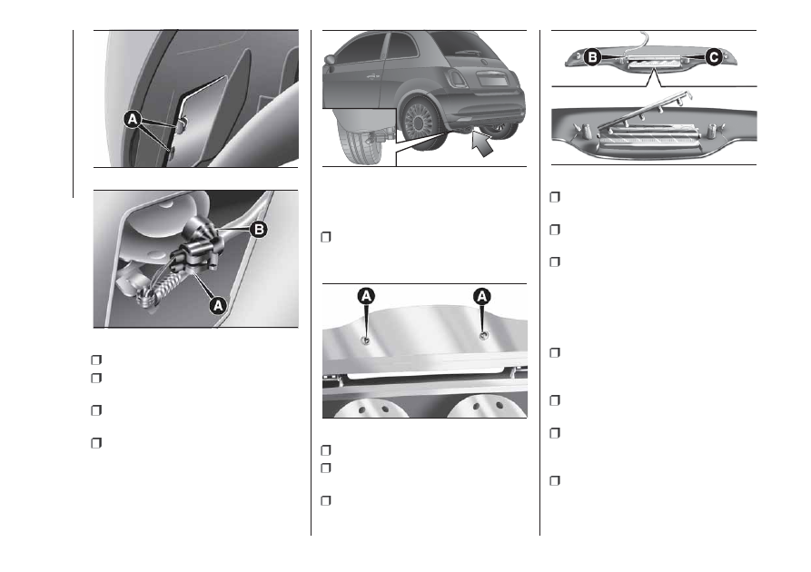
THIRD BRAKE LIGHTS

To replace the bulb proceed as follows:

remove the two guard caps and

unscrew the two fastening screws A fig.
104;

remove the assembly;

disconnect the electrical connector

B fig. 105;

press the retaining device C fig. 105

and open the bulb holder;

remove the press-fitted bulb to be

replaced and replace it;

close the bulb holder making sure

the retaining device is correctly locked;

screw in the two fastening screws

and reinstall the guard caps.

NUMBER PLATE LIGHTS

To replace the bulbs, proceed as
follows:

apply pressure to the point shown

by the arrow fig. 106 and remove
the lens;

change the bulb, releasing it from

the side contacts;

fit the new bulb and make sure that

it is correctly clamped between the
contacts;

then refit the lens.

101

F0S0581

102

F0S0582

103

F0S0674

104

F0S0058

105

F0S0059

120

IN

AN

EMERGENCY

-------------------------------------------------------------------------------------------------------------------------------------------------------------

WARNING

143) Modifications or repairs to the electric
system that are not carried out properly
or do not take the system technical
specifications into account can cause
malfunctions leading to the risk of fire.
144) Halogen bulbs contain pressurised
gas, in the case of breakage they may
burst causing glass fragments to be
projected outwards.
145) Only replace the light bulbs when the
engine is off and in a position that does
not interfere with traffic and lets you safely
replace them (see the description in the
“Replacement” paragraph). Also ensure
that the engine is cold, to prevent the risk
of burns.
146) Before replacing the bulb, wait for the
exhaust ducts to cool down: DANGER
OF SCALDING!

147) Due to the high power supply voltage,
gas discharge bulbs (Xenon) should only
be replaced by specialised personnel:
danger of death! Contact a Fiat Dealership.

WARNING

49) Halogen bulbs must be handled
holding the metallic part only. Touching the
transparent part of the bulb with your
fingers may reduce the intensity of the
emitted light and even reduce the lifespan
of the bulb. In the event of accidental
contact, wipe the bulb with a cloth
moistened with alcohol and let the bulb
dry.
50) Where possible, it is advisable to have
bulbs changed at a Fiat Dealership. The
correct operation and direction of the
external lights are absolutely essential for
the safety of the car and of compliance
with the law.
51) The intervention must be carried out
taking all precautions necessary to avoid
damaging the bodywork (please use a
sufficiently rigid and appropriately thick
plastic card).

REPLACING FUSES

148) 149) 150) 151) 152) 153)

DASHBOARD FUSE BOX

To access the fuses you must remove
the press-fitted cover A fig. 107.

The 5 A fuse B for door mirror
demisting is located in the diagnosis
socket area, as shown in fig. 108.

106

F0S0139

107

F0S0066

108

F0S0677

121

-------------------------------------------------------------------------------------------------------------------------------------------------------------

The dashboard fuse box shown is
located in the lower area next to the
pedal board.

ENGINE COMPARTMENT
JUNCTION BOX

52)

The fusebox is located on the right side
of the engine compartment. To access
the fuses, proceed as follows:

Fully press screw A fig. 109;

at the same time slowly rotate the

screw anticlockwise, until resistance is
encountered (do not overtighten);

slowly release the screw;

opening is indicated by the entire

screw head coming out of its seat;

remove cover B, sliding it upwards

on the side guides, as indicated in
the figure.

Once the fuse has been replaced,
proceed as follows:

correctly refit the cover B in the side

guides of the casing;

slide it down completely from the

top;

fully tighten screw A using the

screwdriver provided;

at the same time slowly rotate the

screw clockwise, until resistance is
encountered (do not overtighten);

slowly release the screw;

closure is indicated by the securing

of the entire screw head in its housing.
The number identifying the electrical
component corresponding to each fuse
is shown on the control unit cover.

LPG versions

The LPG system components are
protected by specific fuses. Contact a
Fiat Dealership for replacement.

109

F0S0606

122

IN

AN

EMERGENCY

-------------------------------------------------------------------------------------------------------------------------------------------------------------

DASHBOARD FUSE BOX

USERS

FUSE

AMPERE

Headlight alignment corrector

F13

5

(*)

Diagnosis socket, radio, climate control, EOBD

F36

15

Brake light switch, instrument panel node

F37

5

Central door locking

F38

15

Windscreen/rear window washer pump

F43

15

Driver side electric window

F47

20

Passenger side electric window

F48

20

(*)(for versions/markets, where provided)

110

F0S0172

123

-------------------------------------------------------------------------------------------------------------------------------------------------------------

USERS

FUSE

AMPERE

Parking sensor, control backlighting, electric mirrors

F49

5

Climate control, brake lights, clutch, electric sunroof, electric
mirrors

F51

7.5

Instrument panel node

F53

5

124

IN

AN

EMERGENCY

-------------------------------------------------------------------------------------------------------------------------------------------------------------

ENGINE COMPARTMENT JUNCTION BOX

USERS

FUSE

AMPERE

HI-FI

F02

20

Climate control electric fan

F08

30

Headlight washers

F09

30

Horns

F10

10

Main-beam headlights

F14

15

Electric roof motor

F15

20

Dualogic gearbox control unit power supply (+ ignition)

F16

7.5

Heated rear window

F20

30

Fog lights

F30

15

Dualogic transmission control unit

F84

10

111

F0S0607

125

-------------------------------------------------------------------------------------------------------------------------------------------------------------

USERS

FUSE

AMPERE

Front power socket (with or without cigar lighter)

F85

20

126

IN

AN

EMERGENCY

-------------------------------------------------------------------------------------------------------------------------------------------------------------

WARNING

148) If the replaced fuse blows again,
contact a Fiat Dealership.
149) Never replace a fuse with metal wires
or anything else.
150) Never replace a fuse with another with
a higher amp rating; DANGER OF FIRE.
151) If a general fuse (MEGA-FUSE,
MIDI-FUSE, MAXI-FUSE) blows contact a
Fiat Dealership.
152) Before replacing a fuse, make sure
that the ignition key has been removed and
that all the other services are switched off
and/or disengaged.
153) Contact Fiat Dealership if a safety
system (airbags, brakes), engine system
(engine, gearbox) or steering system
general protection fuse blows.

WARNING

52) If you need to wash the engine
compartment, take care not to directly hit
the engine compartment fuse box with
the water jet.

REPLACING A
WHEEL

GENERAL
INSTRUCTIONS

154) 155) 156) 157) 158) 159) 160) 161) 162)

JACK

Please note that:

the jack weight is 1.76 kg;

the jack requires no adjustment;

the jack cannot be repaired and in

the event of a fault it must be replaced
by another genuine one;

no tool other than its cranking

device may be fitted on the jack.

MAINTENANCE

prevent any dirt from depositing on

the "worm screw"

keep the "worm screw" lubricated

never modify the jack.

CONDITIONS OF
NON-USE

at temperatures lower than -40°C on

a sandy or muddy ground

on uneven ground

on steep roads

in extreme weather conditions:

thunderstorms, typhoons, hurricanes,
blizzards, storms, etc.

in direct contact with the engine or

for repairs under the car

on boats.

RAISING WITH A JACK
AND REPLACING A
WHEEL

To change a wheel, proceed as follows:

stop the car in a position that is

not dangerous for oncoming traffic
where you can change the wheel safely.
The ground must be flat and sufficiently
compact;

stop the engine, pull up the

handbrake and engage the first gear or
reverse. Wear the reflective safety
jacket (compulsory by law) before
getting out of the car;

raise the mat on the floor of the

luggage compartment;

undo the fastener B fig. 112;

take out the tool box C fig. 112 and

place it next to the wheel to be
changed;

take the space-saver wheel D fig.

112;

for vehicles with wheel cap: use the

screwdriver provided, applying leverage
to the dedicated opening on the outer
edge;

127

-------------------------------------------------------------------------------------------------------------------------------------------------------------

for cars equipped with 15" steel

wheels with aesthetic hub caps: take
the extractor A fig. 113 from the Owner
Handbook compartment;

163)

hold the extractor with two fingers,

insert the tab between the tyre and hub
cap A fig. 114 and pull towards
yourself, perpendicularly to the wheel;

for cars fitted with alloy wheels:

remove the press-fitted hub cap using
the screwdriver provided;

loosen the retaining bolts for the

wheel to be changed by about one turn
using the spanner provided;

if the car is equipped with side

skirts, to let the jack pass under the car,
the latter must be tilted (as shown in
fig. 115);

53)

turn the jack handle to partially open

it;

position the jack near the wheel to

be repaired at the reference point

on

the side member;
Lifting the front wheel: fig. 116.

Lifting the rear wheel: fig. 117.

make sure that the jack fig. 118 is

positioned correctly;

alert any bystander that the car is

about to be raised; all persons should
be kept away from the car and nobody
must touch it until it has been lowered;

112

F0S0127

113

F0S0671

114

F0S0670

115

F0S0328

116

F0S0630

128

IN

AN

EMERGENCY

-------------------------------------------------------------------------------------------------------------------------------------------------------------

fit the handle to operate the jack and

raise the car until the wheel is a few
centimetres above the ground. When
turning the jack handle, make sure that
it can turn freely without scraping
your hand against the ground. The
moving components of the jack (screws
and joints) can also cause injuries:
avoid touching them. If you come into
contact with lubricating grease, clean
yourself thoroughly;

loosen the bolts completely and

remove the wheel to be replaced;

make sure the contact surfaces

between space-saver wheel and hub
are clean so that the fastening bolts will
not come loose;

fit the space-saver wheel aligning

the pin with one of the holes on the
wheel;

screw in the 4 fastening bolts;

turn the jack handle to lower the car

and remove the jack;

fasten the bolts completely, passing

alternately from one bolt to the opposite
one.

REFITTING THE
STANDARD WHEEL

54)

Following the procedure described
previously, raise the car and remove the
space-saver wheel.

Versions with steel wheels

Proceed as follows:

make sure the contact surfaces

between standard wheel and hub are
clean so that the fastening bolts will not
come loose;

fit the standard wheel inserting the 4

bolts into the holes;

using the wrench provided, tighten

the fastening bolts;

lower the vehicle and remove the

jack;

use the wrench provided to fully

tighten the bolts, passing alternately
from one bolt to the opposite one;

insert the pressure-fit cup making

the suitable slot coincide with the
inflation valve;

place the inner part of the hub cap

on the wheel rim;

engage the hub cap by applying an

axial force in several points as shown
in fig. 119 to allow the correct coupling
between hub cap and wheel.

For cars equipped with 15" steel
wheels with aesthetic hub caps:

163)

once the normal wheel has been

fitted, insert the press-fit hub cap,
aligning the slot with the inflation valve;

117

F0S0631

118

F0S0653

119

F0S0632

129

-------------------------------------------------------------------------------------------------------------------------------------------------------------

place the inner part of the hub cap

on the wheel rim;

engage the hub cap by applying an

axial force in several points as shown
in fig. 120 to allow the correct coupling
between hub cap and wheel.

Versions with alloy rims

Proceed as follows:

insert the wheel on the hub and use

the spanner provided to tighten the
bolts;

lower the vehicle and remove the

jack;

use the wrench provided to fully

tighten the bolts in an alternating
sequence;

reinsert the press-fitted hub cap,

making sure that the reference hole on
the wheel is aligned with the reference
pin on the cap.

IMPORTANT If it is not fitted correctly,
the hub cap may detach when the
vehicle is running.

WARNING

154) The space-saver wheel (for
versions/markets where provided) is
specific to your car, do not use it on other
models, or use the space-saver wheel
of other models on your car. The
space-saver wheel must only be used in
the event of an emergency. Never use it for
more than strictly necessary and never
exceed 80 km/h.
155) On the space-saver wheel there is an
orange label, summarising the main
warnings regarding space-saver wheel
usage restrictions. Never remove or cover
the label. The label contains the following
indications in four languages: "Warning! For
temporary use only! 80 km/h max.!
Replace with standard wheel as soon as
possible. Never cover this indication."
Never apply a wheel cap on a space-saver
wheel.
156) If you change the type of wheel (alloy
rims instead of steel rims and vice versa)
you will have to change the entire set
of fastening bolts with another set of
suitably sized bolts.

157) Alert other drivers that the car is
stationary in compliance with local
regulations: hazard warning lights, warning
triangle, etc. Any passengers on board
should leave the car, especially if it is
heavily laden. Passengers should stay
away from on-coming traffic while the
wheel is being changed. On hills or uneven
roads, use chocks or appropriate objects
to block the wheels of the vehicle.
158) The driving features of the car may
change when a space-saver wheel is fitted.
Avoid violent acceleration and braking,
abrupt steering and fast cornering. The
total life of a space-saver wheel is
approximately 3,000 km, after which it
must be replaced by another wheel of the
same type. Never install a traditional tyre
on a rim designed to be used as a
space-saver wheel. Have the wheel
repaired and refitted as soon as possible.
Using two or more space-saver wheels
at the same time is forbidden. Do not apply
grease to the bolt threads before fitting:
they could come unscrewed.

120

F0S0669

130

IN

AN

EMERGENCY

-------------------------------------------------------------------------------------------------------------------------------------------------------------

159) The jack is a tool developed and
designed only for changing a wheel, if a
tyre gets punctured or damaged, on the
vehicle with which it is supplied or on other
vehicles of the same model. Any other
use, e.g. to jack up other vehicle models or
different things, is strictly prohibited. Never
use it to carry out maintenance or repairs
under the vehicle or to change summer/
winter wheels and vice versa. Never go
under the raised vehicle. If any work under
the vehicle is necessary, contact the Fiat
Service Network. Incorrect placing of
the jack can cause the vehicle to drop: use
it only in the positions indicated. Do not
use the jack for loads higher than the one
shown on its label. Never start the engine
with vehicle raised. If the vehicle is raised
more than necessary, everything can
become more unstable, with the risk of the
vehicle dropping violently. Thus, lift the
vehicle only as needed in order to access
the spare tyre.
160) Snow chains cannot be fitted to the
space-saver wheel. So, if a front (drive)
wheel is punctured and chains are needed,
a rear wheel should be fitted to the front
of the car and the space-saver wheel
should be fitted to the rear. In this way,
equipped with two normal drive wheels at
the front, they can be fitted with snow
chains, thus resolving the emergency
situation.
161) If the hub cap is not fitted correctly, it
may come off when the car is travelling.
Never tamper with the inflation valve. Never
introduce tools of any kind between rim
and tyre. Check tyre and space-saver
wheel pressures regularly, complying with
the values given in the "Technical
specifications" chapter.

162) It is extremely dangerous to attempt
to change a wheel on the side of the
vehicle next to the driving lane: make sure
that the vehicle is at a sufficient distance
from the road, to avoid being run over.
163) Be very careful when removing/
refitting the hub cap due to the proximity of
the brake disc. We recommend using
heat protection gloves.

WARNING

53) When turning the jack handle make
sure that it can turn freely without scraping
your hand against the ground. The moving
components of the jack ("worm screw"
and joints) can also cause injuries: do not
touch them. If you come into contact
with lubricating grease, clean yourself
thoroughly.
54) Contact a Fiat Dealership as soon as
possible to have the correct tightening
of the wheel bolts checked.

Fix&Go kit

(where provided)

164) 165)

55)

DESCRIPTION

The Fix&Go quick tyre repair kit fig. 121
is located in the boot, inside a
dedicated container and consists of:

one cartridge 1 containing sealant

and fitted with: transparent tube for
injecting the sealant 4 and sticker
3 with the wording “Max 80 km/h” to
be placed in a clearly visible position
(e.g. on the dashboard) after repairing
the tyre;

one compressor 2;

one leaflet containing instructions for

using the kit;

a pair of gloves located in the hose

compartment of the cartridge 4.

121

P2000158

131

-------------------------------------------------------------------------------------------------------------------------------------------------------------

REPAIR PROCEDURE

Proceed as follows:

stop the car in a position that is not

dangerous for oncoming traffic where
you can carry out the procedure safely.
The ground must be flat and sufficiently
compact;

stop the engine, engage the hazard

warning lights and the parking brake;

wear the reflective safety jacket

before getting out of the car (anyway
comply with the laws in force in the
country you are driving in);

Insert the cartridge 1 containing the

sealant in the proper compartment of
the compressor 2, pressing it down
hard fig. 121. Remove the speed limit
sticker 3 and apply it in a clearly visible
position fig. 122;

wear the gloves;

remove the cap from the tyre valve

and connect and firmly tighten the
transparent tube of the sealing fluid 4
fig. 121. If a 250 ml cartridge is present
the housing of the transparent tube is
provided with removable ring to
facilitate extraction. Make sure that the
ON-OFF button 5 fig. 123 is in the off
position (button not pressed);

plug the electric connector 3 fig. 124

into the 12V socket of the vehicle and
start the vehicle engine;

operate the compressor by pressing

the ON-OFF button 5 fig. 123. When
the pressure shown in the "Wheels"
paragraph in the “Technical data”
chapter or on the specific label appears
on the pressure gauge 7, stop the
compressor by pressing the ON-OFF
button 5 again;

disconnect the cartridge 1 from the

compressor, by pressing the release
button 8 and lifting the cartridge 1
upwards fig. 125.

122

P2000162

123

P2000160

124

P2000159

125

P2000161

132

IN

AN

EMERGENCY

-------------------------------------------------------------------------------------------------------------------------------------------------------------

If the pressure gauge 7 fig. 123
indicates a pressure lower than 1.8 bar
/ 26 psi 15 minutes after starting the
compressor, switch off the compressor,
disconnect the sealing fluid tube 4
from the tyre valve and remove
the cartridge 1 from the compressor fig.
121. Move the vehicle by approximately
10 m to promote the distribution of
sealant; stop the vehicle safely, operate
the handbrake and restore pressure
using the black inflation pipe 9 fig. 126
to reach the required pressure. If also
in this case, the pressure is lower
than 1.8 bar / 26 psi 15 minutes after
turning on, do not resume driving
but contact a Fiat Dealership.

After driving for about 8 km / 5 miles,
position the vehicle in a safe and
suitable area and engage the
handbrake. Take the compressor and
restore pressure using the black
inflation tube 9 fig. 126.
If the pressure shown is higher than 1.8
bar / 26 psi, restore the pressure and
drive safely to a Fiat Dealership as soon
as possible.
If, however, the pressure is lower than
1.8 bar / 26 psi, do not resume driving
but contact a Fiat Dealership.

PROCEDURE FOR
RESTORING THE
PRESSURE

Proceed as follows:

stop the vehicle safely, as shown

above, and operate the handbrake;

extract the black inflation tube 9 fig.

126 and screw it firmly onto the tyre
valve. Follow the instructions shown in
fig. 124 and fig. 126.
Press the air release button 10 fig. 123
to adjust any tyre overpressure.

CARTRIDGE
REPLACEMENT

Proceed as follows:

only use original Fix&Go cartridges,

which can be purchased from the
Fiat Dealership.

to remove the cartridge,fig. 125

press the release button 8 and lift it.

WARNING

164) The information required by the
applicable regulation is indicated on the
Fix&Go kit package label. Carefully read
the label on the cartridge before use, avoid
improper use. The kit should be used by
adults and cannot be used by children.
165) IMPORTANT: Do not exceed 80 km/h.
Avoid sudden acceleration or braking.
The kit provides a temporary repair,
therefore the tyre must be examined and
repaired by a specialist as soon as
possible. Before using the kit, ensure that
the tyre is not excessively damaged and
that the rim is in good condition, otherwise
do not use it and call roadside assistance.
Do not remove foreign bodies from the
tyre. Do not let the compressor turned on
for more than 20 consecutive minutes -
overheating hazard.

WARNING

55) The sealant fluid is effective with
external temperatures between -40°C and
+55°C. The sealant fluid has an expiry
date. It is possible to repair tyres which
have been damaged on tread up to a
diameter of 6 mm. Show the cartridge and
the label to the personnel charged with
handling the tyre treated with the tyre
repair kit.

126

P2000163

133

-------------------------------------------------------------------------------------------------------------------------------------------------------------

JUMP STARTING

If the battery is flat, a jump starting can
be performed using the battery and
the cables of another car, or using an
auxiliary battery. In all cases, the battery
used must have a capacity equal to or
a little higher than the flat one.
Jump starting may be dangerous if
carried out incorrectly: carefully follow
the procedures described below.

IMPORTANT NOTES

After turning the ignition key to STOP
and having closed the driver's side
door, wait at least one minute before
disconnecting the battery and then
reconnecting the electrical supply to the
battery.
Do not use an auxiliary battery or any
other source of external supply with
a voltage above 12 V: the battery, the
starter, the alternator and the electrical
system of the car could be damaged.
Do not attempt jump starting if the
battery is frozen. The battery could
break and explode!

JUMP STARTING

166) 167) 168)

56) 57) 58)

If the battery is flat, the engine may be
started using an auxiliary battery fig.
127, with the same capacity or a little
higher than the flat one.

Proceed as follows to start the car:

connect the positive terminals (+

mark near the terminal) of the two
batteries using a suitable lead;

with a second lead, connect the

negative terminal – of the auxiliary
battery to an earth point

on

the engine or the gearbox of the car to
be started;

start the engine;

when the engine has been started,

remove the leads reversing the order
above.

For versions with Start&Stop

In the case of emergency starting,
NEVER connect the negative lead (–) of
the auxiliary battery to negative pole
(–) of the battery, but only to an earth
point on the engine/gearbox assembly.
If after a few attempts the engine does
not start, do not persist but contact
a Fiat Dealership.

IMPORTANT Do not directly connect
the negative terminals of the two
batteries: sparks could ignite explosive
gas released from the battery. If the
auxiliary battery is installed on another
car, prevent accidental contact
between metallic parts of the two cars.

BUMP STARTING

Never bump start the engine by
pushing, towing or driving downhill.
This could cause fuel to flow into the
catalytic converter and damage it
beyond repair.

IMPORTANT Remember that the brake
servo and electrical power steering
system (for versions/markets, where
provided) are not active until the engine
is started. A much greater effort will
therefore be required to use the brake
pedal or turn the steering wheel.

127

F0S0093

134

IN

AN

EMERGENCY

-------------------------------------------------------------------------------------------------------------------------------------------------------------

WARNING

166) This starting procedure must be
performed by expert personnel because
incorrect actions could cause electrical
discharge of considerable intensity.
Furthermore, battery fluid is poisonous and
corrosive: avoid contact with skin and
eyes. Keep naked flames and lighted
cigarettes away from the battery and do
not cause sparks.
167) Remove any metal objects (e.g. rings,
watches, bracelets), that might cause an
accidental electrical contact and cause
serious injury.
168) Do not attempt to charge a frozen
battery: it must be thawed first, otherwise it
may explode. If freezing has occurred, the
battery should be checked by skilled
personnel to make sure that the internal
elements are not damaged and that the
body is not cracked, with the risk of leaking
poisonous and corrosive acid.

WARNING

56) Never use a fast battery-charger to
start the engine as this could damage the
electronic systems of your vehicle,
particularly the ignition and engine fuel
supply control units.

57) Do not connect the cable to the
negative terminal (–) of the flat battery. The
following spark could lead to battery
explosion and cause serious harm. Only
use the specific earth point; do not use any
other exposed metallic part.
58) Never bump start the engine by
pushing, towing or coasting downhill. This
could cause fuel to flow into the catalytic
converter and damage it beyond repair.

FUEL CUT-OFF
SYSTEM

169)

This intervenes in the case of an impact
causing:

the fuel supply cut-off with the

engine consequently switching off

the automatic unlocking of the doors

turning on of the lights inside the

vehicle;
The intervention of the system is
indicated by a message shown on the
display.

IMPORTANT Carefully check the car for
fuel leaks, for instance in the engine
compartment, under the car or near the
tank area. After a collision, turn the
ignition key to STOP position to prevent
the battery from running down.
To restore the correct operation of the
vehicle, proceed as follows:

turn the ignition key to the MAR-ON

position

activate the right direction indicator

deactivate the right direction

indicator

activate the left direction indicator

deactivate the left direction indicator

135

-------------------------------------------------------------------------------------------------------------------------------------------------------------


Content      ..     6      7      8      9     ..