HM484Q Engine. Manual - part 8


  Index      FAW     HM484Q Engine (Haima 7) - service manual


Search            


Content   ..  6  7  8  9   ..


HM484Q Engine. Manual - part 8


Ignition and control systems 

23 

Ignition and control systems 

Lubrication system of ignition and PVC valve   

Caution 

l  When removing the ignition coil and spark plug, it is very easy to tear up the 

extension bar sheath, therefore, disassemble it when the replacement is 
necessary. At the disassembly time, be cautious to avoid tearing or damage. 

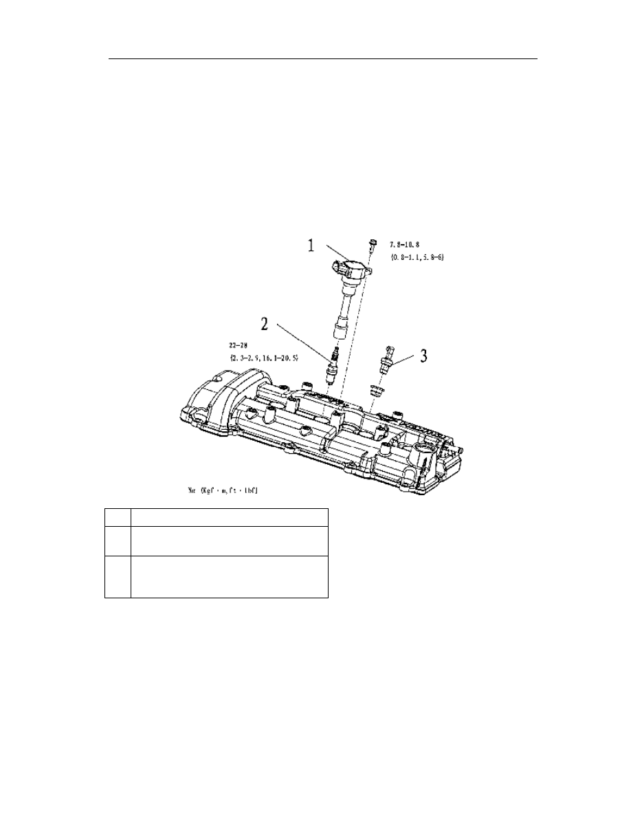
1.  Disassemble in the order as shown in Fig. 

2.  Assemble in the reversing order of disassembly. 


Ignition coil   

Spark plug (See

——Removal/Installation 

of Spark Plug) 

Positive Crankcase 
Ventilation(PCV)valve (See

——Check of 

PVC valve) 


Instructions of plug removal/installation 

Caution 

l  The spark plugs have to be carefully fitted, as the powerful strike will result in 

spark plug damage. 


Ignition and control systems 

24 

Check of PVC valve 

1.  Dismantle the PCV valve. 

2.  Confirm  the  ventilation  of  PCV  valve 

behaves as shown in the Table. 

l  Replace if abnormal. 


Table of ventilation 

Testing condition 

Result of testing 

Blow into the joint A 

Air outlets from the joint B 

Blow into the joint B 

No air outlets from the joint A 


Ignition and control systems 

25 

Disassembly/assembly of control system parts 

1.  Disassemble as per the order shown in Fig. 

2.  Assemble in the reversing order of disassembly. 


1


Crankshaft position sensor 
(See

——Check of Crankshaft Position 

Sensor) 

2


Oil control valve 

3


Water temperature sensor (See

—— 

Instructions of Removal and 
Installation) 

4


Knock sensor   

5


Injector   

6


Fuel rail   

7


Electronic throttle body   

8


Cam position sensor   

*Note 1: This part has only listed the installations all parts of control system on the engine. The 
relevant diagnostics and checks are referred to the corresponding part of CBU. 


Ignition and control systems 

26 


Removal/installation instructions of water temperature sensor 

Use a special tool to disassemble/assemble the water temperature sensor. 


Check of crankshaft position sensor 

Check of clearance 

Attention 

l  Do the following checks only when necessary. 

1.  Confirm that the crankshaft speed sensor has been correctly installed. 

2.  Use a feeler to measure the clearance between the platform of signal wheel protrusion and 

crankshaft speed sensor. 

l  If in wrong clearance, you may adjust the crankshaft speed sensor or check for 

any distortion and notch in the signal wheel protrusion(If yes, you should 
replace the crankshaft pulley. See Timing Sprocket

——Disassembly 

Instructions of Crankshaft Pulley). 


Standard value 


0.5~1.1mm(0.020~0.043in) 


Special sleeve 

Clearance 

Crankshaft speed sensor 

Crankshaft pulley 

Protrusion 

platform 


Content   ..  6  7  8  9   ..