Abarth 500 (2019 year). Manual in english - page 6
 

  Index      Manuals     Abarth 500 (2019 year). Manual in english


Search            copyright infringement  


Content      ..     4      5      6      7     ..


Abarth 500 (2019 year). Manual in english - page 6


PARKING SENSORS

(where provided)

Parking sensors are located in the rear
bumper to detect and inform the driver,
through an acoustic and visual warning,
of the presence of obstacles at the
rear part of the car. The sound may be
intermittent or continuous depending
on the distance from the obstacle.

ACTIVATION

The sensors are automatically activated
when reverse gear is engaged. As the
obstacle behind the vehicle gets closer
to the car, the acoustic signal becomes
more frequent.

ACOUSTIC SIGNAL

When reverse gear is engaged and
there is an obstacle behind the car, an
acoustic warning is activated. The
frequency of the acoustic warning
increases as the distance between the
obstacle and the bumper decreases,
becoming continuous when the
distance is less than 30 cm.

Detection distances

If several obstacles are detected by the
sensors, only the nearest one is
considered.

When parking, take the utmost care
over obstacles that may be above
or under the sensor.
Objects close to the car are not
detected under certain circumstances
and could therefore cause damage
to the car or be damaged.

114)

23) 24)

INDICATIONS ON
DISPLAY

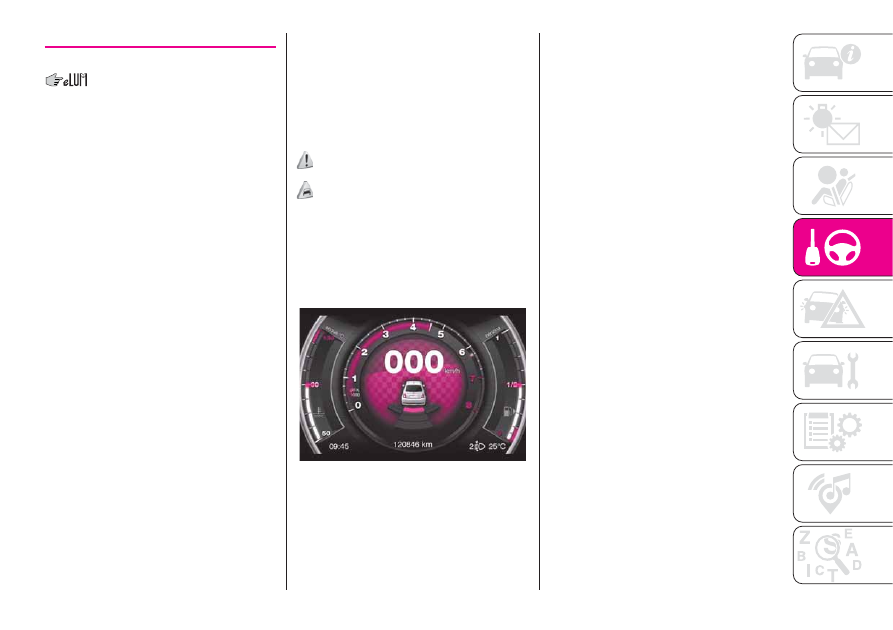
When the sensors are activated, the
screen shown in fig. 81 appears on the
display.

In addition to the acoustic warning,
information about the presence and
distance from the obstacle is given
visually on the instrument panel display.
The coloured arcs at the rear of the
car indicate that an obstacle has been
detected. The system indicates a
detected obstacle by displaying an arc
according to the distance of the
obstacle and its position in relation to
the car. If an objects is detected to the
rear of the car (to the side or at the
centre), the display shows an flashing
arc in the corresponding zone and
an intermittent sound is emitted. As the
car approaches the object, the display
shows one or more flashing arcs that
approach the car, and the sound
becomes more frequent until it
becomes continuous. The colour on the
display depends on the distance from
and position of the obstacle. As the
distance between the car and obstacle
decreases, the arcs change from yellow
to flashing red (to the right, at the
centre or to the left).

81

AB0A0390C

91

-------------------------------------------------------------------------------------------------------------------------------------------------------------

WARNING

23)

For correct operation of the system,

sensors must always be clean from mud,
dirt, snow or ice. Be careful not to scratch
or damage the sensors while cleaning
them. Avoid using dry, rough or hard
cloths. The sensors must be washed using
clean water, with the addition of vehicle
shampoo if necessary. When using special
washing equipment such as high pressure
jets or steam cleaning, clean the sensors
very quickly keeping the jet more than
10 cm away.

24)

Have interventions on the bumper in

the area of the sensors carried out only by
an Abarth Dealership. Interventions on
the bumper that are not carried out
properly may compromise the operation of
the parking sensors.

WARNING

114)

Parking and other dangerous

manoeuvres are, however, always the
driver’s responsibility. While carrying out
these manoeuvres, always make sure that
no people (especially children) or animals
are in the area concerned. The parking
sensors are an aid for the driver, but the
driver must never allow their attention
to lapse during potentially dangerous
manoeuvres, even those executed at low
speeds.

REFUELLING THE
VEHICLE

Stop the engine before refuelling.

IMPORTANT Never introduce leaded
petrol to the tank, even in small
amounts in an emergency, as this
would damage the catalytic converter
beyond repair.

REFUELLING CAPACITY

To ensure that you fill the tank
completely, top up twice after the first
click of the fuel supply gun. Further
top-ups could cause faults in the fuel
supply system.

FUEL TANK CAP

Plug 2 fig. 82 is fitted with a cable that
secures it to flap 1 so that it cannot
be lost.

Unscrew cap 2 using the ignition key.
The sealing may cause a slight pressure
increase in the tank. A little breathing
off, while slackening the cap is
absolutely normal. When refuelling,
fasten the plug to the device inside the
flap as shown in fig. 82.

115)

82

AB0A0058C

92

ST

AR

TING

AND

DRIVING

-------------------------------------------------------------------------------------------------------------------------------------------------------------

Fuels - identification of
vehicle compatibility.
Graphic symbol for
consumer information in
accordance with
EN16942

The symbols shown below facilitated
recognising the correct fuel type to
be used on your car.
Before proceeding with refuelling,
check the symbols inside the fuel filler
flap (where provided) and compare
them with the symbols shown on the
fuel pump (where provided).

Symbols for petrol powered cars

E5:

Unleaded petrol containing up to

2.7% (m/m) oxygen and with maximum
5.0% (V/V) ethanol compliant with

EN228

.

E10:

Unleaded petrol containing up to

3.7% (m/m) oxygen and with maximum
10.0% (V/V) ethanol compliant with

EN228

.

WARNING

115)

Do not approach naked flames or lit

cigarettes to the fuel tank filler: fire risk.
Keep your face away from the fuel filler to
prevent breathing in harmful vapours.

93

-------------------------------------------------------------------------------------------------------------------------------------------------------------

IN AN EMERGENCY

A punctured tyre or a burnt-out bulb?

At times, a problem may interfere
with our journey.

The pages on emergencies can help
you to deal with critical situations
independently and with calm.

In an emergency we recommend that
you call the freephone number found in
the Warranty Booklet.

It is also possible to call the 00 800
3428 0000 freephone number to
search the nearest Abarth Authorised
Dealership.

HAZARD WARNING LIGHTS........... 95

CHANGING A BULB ....................... 95

REPLACING AN EXTERIOR BULB ..100

REPLACING FUSES........................103

“FIX&GO” KIT ..................................108

JUMP STARTING ............................110

FUEL CUT-OFF SYSTEM ................111

TOWING THE VEHICLE ..................112

94

IN

AN

EMERGENCY

-------------------------------------------------------------------------------------------------------------------------------------------------------------

HAZARD WARNING
LIGHTS

These lights are turned on by pressing

the button 1 fig. 83, regardless of the
position of the ignition key.
With the device on, warning lights

and

light up in the instrument

panel.
Press the button 1 again to switch the
lights off.

IMPORTANT The use of hazard warning
lights is governed by the highway
code of the country you are driving in:
comply with legal requirements.

Emergency braking

In the event of an emergency braking,
the hazard warning lights switch on
automatically together with warning
lights

and

on the instrument

panel.

The lights switch off automatically when
emergency braking ceases.

CHANGING A BULB

GENERAL
INSTRUCTIONS

Before replacing a bulb check the

contacts for oxidation;

burnt bulbs must be replaced by

others of the same type and power;

always check the headlight beam

direction after changing a bulb;

when a light is not working, check

that the corresponding fuse is intact
before replacing a bulb. For the location
of fuses, refer to the paragraph
"Replacing fuses" in this chapter.

116) 117) 118) 119)

25) 26)

83

AB0A0350C

95

-------------------------------------------------------------------------------------------------------------------------------------------------------------

IMPORTANT When the weather is cold
or damp or after heavy rain or washing,
the surface of headlights or rear lights
may steam up and/or form drops of
condensation on the inside. This is
a natural phenomenon due to the
difference in temperature and humidity
between the inside and the outside
of the glass which does not indicate a
fault and does not compromise the
normal operation of lighting devices.
The mist disappears quickly when the
lights are turned on, starting from
the centre of the diffuser, extending
progressively towards the edges

96

IN

AN

EMERGENCY

-------------------------------------------------------------------------------------------------------------------------------------------------------------

BULBS TYPES

Various types of bulbs are fitted to your car:

All-glass bulb:

(type A) these are pressure fitted - pull to remove.

Bayonet bulb:

(type B) to remove them press the bulb and turn it

anticlockwise.

Cylindrical bulbs:

(type C) release them from their contacts to remove.

Halogen bulbs:

(type D) to remove the bulb, release the clip holding

the bulb in place.

Halogen bulbs:

(type E) to remove the bulb, release the clip holding

the bulb in place.

Xenon gas discharge bulbs:

(type F) contact an Abarth Dealership for replacement.

97

-------------------------------------------------------------------------------------------------------------------------------------------------------------

Light bulbs

Use

Type

Power

Ref. Figure

Main beams

H7

55W

D

Dipped headlights

H7

55W

D

Xenon gas discharge dipped beam headlights (where
present)

D1S

35W

F

Front side lights/day lights

LED/W21W

21W

A

Front direction indicators

PY24W

24W

B

Side turn light

W5W

5W

A

Rear direction indicators

PY2IW

2IW

B

Rear side lights/Brake lights

P21/5W

5/21W

B

Reverse gear

W16W

16W

B

Rear fog light

W16W

16W

B

Centre courtesy light

C5W

5W

C

Passenger side courtesy light

C5W

5W

C

Boot light

W5W

5W

A

Number plate light

C5W

5W

C

Fog lights

HI

55W

E

Third brake lights

W5W

5W

A

98

IN

AN

EMERGENCY

-------------------------------------------------------------------------------------------------------------------------------------------------------------

WARNING

116)

Modifications or repairs to the electric system that are not carried out properly or do not take the system technical specifications into

account can cause malfunctions leading to the risk of fire.

117)

Halogen bulbs contain pressurised gas, in the case of breakage they may burst causing glass fragments to be projected outwards.

118)

Before replacing the bulb, wait for the exhaust ducts to cool down: DANGER OF SCALDING!

119)

Only replace the light bulbs when the engine is off and in a position that does not interfere with traffic and lets you safely replace them

(see the description in the “Replacement” paragraph). Also ensure that the engine is cold, to prevent the risk of burns.

WARNING

25)

Halogen bulbs must be handled holding the metallic part only. Touching the transparent part of the bulb with your fingers may reduce the

intensity of the emitted light and even reduce the lifespan of the bulb. In the event of accidental contact, wipe the bulb with a cloth moistened
with alcohol and let the bulb dry.

26)

Where possible, it is advisable to have bulbs changed at an Abarth Dealership. The correct operation and direction of the external lights

are absolutely essential for the safety of the car and of compliance with the law.

99

-------------------------------------------------------------------------------------------------------------------------------------------------------------

REPLACING AN
EXTERIOR BULB

For the type of bulb and power rating,
see paragraph "Replacing a bulb".

FRONT LIGHT CLUSTERS

The front light clusters contain side
lights, dipped headlights, main beam
headlights and direction indicator bulbs.

Access to the direction indicator
bulbs

Working from the engine compartment,
remove the rubber cap 1 fig. 84.

Access to the main beam headlight
bulbs

Rotate the cap 2 fig. 84 anticlockwise.

Access to the daytime running light
(DRL) and main beam headlight
bulbs

Completely steer the wheels and open
guard door 3 fig. 85 (on the wheel
arch at the level of the lights) then
remove the rubber cap 4 fig. 85.

DIRECTION INDICATORS

Front

To replace the bulb, proceed as follows:

turn the protection cap 1 fig. 84

anticlockwise and remove it;

turn the bulb holder 1 fig. 86

anticlockwise and remove it;

remove the pressure-fitted bulb and

replace it;

refit the bulb holder 1 by turning it

clockwise and locking it correctly;

insert the protection cap and turn it

clockwise.

Side

IMPORTANT The intervention must be
carried out taking all precautions
necessary to avoid damaging the
bodywork (use a sufficiently rigid and
appropriately thick plastic card).

To replace the bulb, proceed as follows:

apply leverage at the point indicated

by the arrows 1 and 2, in such a way
as to compress the fixing clip and
remove the light fig. 87

84

AB0A0309C

85

AB0A0089C

86

AB0A0361C

87

AB0A0310C

100

IN

AN

EMERGENCY

-------------------------------------------------------------------------------------------------------------------------------------------------------------

turn the bulb holder anticlockwise,

extract the press-fitted bulb and
replace it;

refit the bulb holder in the lens, then

position the light, ensuring that the
fastening clip clicks into place.

DIPPED HEADLIGHTS

To replace the bulb, proceed as follows:

turn the protection cap 2 fig. 84

anticlockwise and remove it;

disconnect the connector 1 fig. 88

and release the bulb holder;

extract the bulb and replace it;

refit the bulb in its seat and

reconnect the connector;

refit the protection cap in its housing

and turn clockwise.

120)

MAIN BEAM HEADLIGHTS

To replace the bulb, proceed as
follows:

remove the protective rubber cap

mentioned above;

release the two bulb holding clips 1

fig. 89;

extract the bulb and replace it;

fit the new bulb, making the outline

of the metallic part coincide with the
grooves on the reflector, then reattach
the bulb holding clips;

refit the rubber cap.

SIDE LIGHTS/DAYTIME
RUNNING LIGHTS

To replace the bulb, proceed as follows:

remove the protective rubber cap

mentioned above;

turn the bulb holder 2 fig. 89

anticlockwise and remove it;

remove the pressure-fitted bulb and

replace it;

refit the bulb holder 2 by turning it

clockwise and locking it correctly;

refit the rubber cap.

FRONT FOG LIGHTS

(where provided)

For replacing these bulbs, contact an
Abarth Dealership.

REAR LIGHT CLUSTERS

To replace the bulb proceed as follows:

open the tailgate;

unscrew the two fastening screws 1

fig. 90 and extract the light cluster
axially without rotating it;

remove the bulb holder from its

housing releasing it from the locking
tabs 2;

extract the bulbs by pushing them

slightly and turning them anticlockwise.

88

AB0A0311C

89

AB0A0093C

90

AB0A0313C

101

-------------------------------------------------------------------------------------------------------------------------------------------------------------

The bulbs are arranged as follows fig.
91:
1: side / brake light;
2: direction indicators.

REVERSING LIGHT/REAR
FOG LIGHT

For bulb replacement, contact an
Abarth Dealership.

THIRD BRAKE LIGHTS

To replace the bulb proceed as follows:

remove the two guard caps and

unscrew the two fastening screws 1 fig.
92;

remove the assembly;

disconnect the electrical connector

2 fig. 93;

press the retaining device 3 fig. 93

and open the bulb holder;

remove the press-fitted bulb to be

replaced and replace it;

close the bulb holder making sure

the retaining device is correctly locked;

screw in the two fastening screws

and reinstall the guard caps.

NUMBER PLATE LIGHTS

To replace the bulbs, proceed as
follows:

apply pressure to the point shown

by the arrow fig. 94 and remove the
lens;

change the bulb, releasing it from

the side contacts;

fit the new bulb and make sure that

it is correctly clamped between the
contacts;

then refit the lens.

WARNING

120)

Due to the high power supply

voltage, gas discharge bulbs (Xenon)
should only be replaced by specialised
personnel: danger of death! Contact
an Abarth Dealership.

91

AB0A0314C

92

AB0A0097C

93

AB0A0098C

94

AB0A0099C

102

IN

AN

EMERGENCY

-------------------------------------------------------------------------------------------------------------------------------------------------------------

REPLACING FUSES

GENERAL INFORMATION

Fuses protect the electrical system:
they intervene (blow) in the event of a
failure or improper action on the
system.

121) 122) 123) 124) 125) 126)

To facilitate fuse replacement, use the
pliers hooked inside the fuse box lid on
the dashboard left-hand side.
Refer to the tables on the following
pages to identify the protective fuse.

FUSE LOCATION

Dashboard fuse box

To access the fuse you must remove
the press-fit cover 5 fig. 95.

The 5 A fuse for door mirror demisting
is located in the diagnosis socket
area, as shown in fig. 96.

The fuse box shown in fig. 98 is located
in the lower area next to the pedal
unit.

Engine compartment
junction box

The fuse box is located on the right
side of the engine compartment, next
to the battery. To access the fuses,
proceed as follows:

Fully tighten the screw 1 fig. 97;

at the same time slowly rotate the

screw anticlockwise, until resistance is
encountered (do not overtighten);

slowly release the screw;

opening is indicated by the entire

screw head coming out of its housing;

remove cover 2, sliding it upwards

on the side guides, as indicated in
the figure;

after replacing the fuse, refit the

cover, making sure that it is closed
properly.
The number identifying the electrical
component corresponding to each fuse
is shown on the cover fig. 99.

27)

95

AB0A0291C

96

AB0A0317C

97

AB0A0375C

103

-------------------------------------------------------------------------------------------------------------------------------------------------------------

DASHBOARD FUSE BOX

DEVICE PROTECTED

FUSE

AMPERE

Headlight alignment corrector

F13

5

(*)

Diagnosis socket, Uconnect, climate control, EOBD

F36

15

Brake light switch, instrument panel node

F37

5

Central door locking

F38

15

Windscreen/rear window washer pump

F43

15

Driver's side electric windows

F47

20

(*) (where provided)

98

AB0A0106C

104

IN

AN

EMERGENCY

-------------------------------------------------------------------------------------------------------------------------------------------------------------

DEVICE PROTECTED

FUSE

AMPERE

Passenger side electric window

F48

20

Parking sensor, controls backlighting

F49

5

Climate control, brake lights, clutch, electric sunroof, electric
mirrors

F51

7.5

Instrument panel node

F53

5

105

-------------------------------------------------------------------------------------------------------------------------------------------------------------

ENGINE COMPARTMENT JUNCTION BOX

DEVICE PROTECTED

FUSE

AMPERE

HI-FI

F02

20

Climate control electric fan

F08

30

Headlight washers

F09

30

Horns

F10

10

Main-beam headlights

F14

10/15

(*)

Electric roof motor

F15

20

(*) Only for versions equipped with Xenon gas discharge lamps

99

AB0A0319C

106

IN

AN

EMERGENCY

-------------------------------------------------------------------------------------------------------------------------------------------------------------


Content      ..     4      5      6      7     ..