Dodge Durango (2022 year). Manual in english - page 8
 

  Index      Manuals     Dodge Durango (2022 year). Manual in english


Search            copyright infringement  


Content      ..     6      7      8      9     ..


Dodge Durango (2022 year). Manual in english - page 8


122

STARTING AND OPERATING


To Vary The Speed Setting 

To Increase Or Decrease The Set Speed
After setting a speed, you can increase the set 

speed by pushing the SET (+) button, or decrease 

speed by pushing the SET (-) button.
U.S. Speed (mph)

Pushing the SET (+), or SET (-) button once will 

result in a 1 mph speed adjustment. Each 

subsequent tap of the button results in an 

adjustment of 1 mph.

If the button is continually pushed, the set 

speed will continue to adjust in 5 mph incre

-

ments until the button is released. The new set 

speed is reflected in the instrument cluster 

display.

Metric Speed (km/h)

Pushing the SET (+), or SET (-) button once will 

result in a 1 km/h speed adjustment. Each 

subsequent tap of the button results in an 

adjustment of 1 km/h.

If the button is continually pushed, the set 

speed will continue to adjust in 10 km/h incre

-

ments until the button is released. The new set 

speed is reflected in the instrument cluster 

display.

NOTE:

When you override and push the SET (+) button or 

SET (-) button, the new set speed will be the current 

speed of the vehicle.
When ACC Is Active:

When you use the SET (-) button to decelerate, if 

the engine’s braking power does not slow the 

vehicle sufficiently to reach the set speed, the 

brake system will automatically slow the 

vehicle.

The ACC system applies the brake down to a full 

stop when following the vehicle in front. If your 

vehicle follows the vehicle in front to a standstill, 

your vehicle will release the brakes two seconds 

after coming to a full stop.

The ACC system maintains set speed when 

driving uphill and downhill. However, a slight 

speed change on moderate hills is normal. In 

addition, downshifting may occur while climbing 

uphill or descending downhill. This is normal 

operation and necessary to maintain set speed. 

When driving uphill and downhill, the ACC 

system will cancel if the braking temperature 

exceeds normal range (overheated).

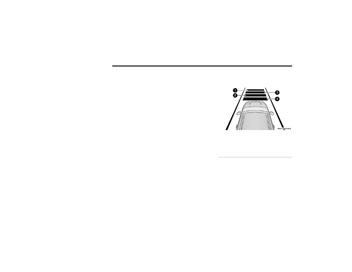
Setting The Following Distance In ACC

The specified following distance for ACC can be set 

by varying the distance setting between four bars 

(longest), three bars (long), two bars (medium) and 

one bar (short). Using this distance setting and the 

vehicle speed, ACC calculates and sets the 

distance to the vehicle ahead. This distance 

setting appears in the instrument cluster display.

Distance Settings

To increase the distance setting, push the 

Distance Increase button and release. Each time 

the button is pushed, the distance setting 

increases by one bar (longer).
To decrease the distance setting, push the 

Distance Decrease button and release. Each time 

the button is pushed, the distance setting 

decreases by one bar (shorter).

1 — Longest Distance Setting (Four Bars)
2 — Medium Distance Setting (Two Bars)
3 — Long Distance Setting (Three Bars)
4 — Short Distance Setting (One Bar)

STARTING AND OPERATING

123

If there is no vehicle ahead, the vehicle will 

maintain the set speed. If a slower moving vehicle 

is detected in the same lane, the instrument 

cluster display will show the ACC Set With Target 

Detected Indicator Light. The system will then 

adjust the vehicle speed automatically to maintain 

the distance setting, regardless of the set speed.
The vehicle will then maintain the set distance 

until:

The vehicle ahead accelerates to a speed above 

the set speed.

The vehicle ahead moves out of your lane or 

view of the sensor.

The distance setting is changed.

The system disengages  

Ú

page 120.

The maximum braking applied by ACC is limited; 

however, the driver can always apply the brakes 

manually, if necessary.
NOTE:

The brake lights will illuminate whenever the ACC 

system applies the brakes.
A Proximity Warning will alert the driver if ACC 

predicts that its maximum braking level is not 

sufficient to maintain the set distance. If this 

occurs, a visual alert “BRAKE!” will flash in the 

instrument cluster display and a chime will sound 

while ACC continues to apply its maximum braking 

capacity.

NOTE:

The “BRAKE!” screen in the instrument cluster 

display is a warning for the driver to take action 

and does not necessarily mean that the Forward 

Collision Warning system is applying the brakes 

autonomously.

Overtake Aid

When driving with Adaptive Cruise Control (ACC) 

engaged and following a vehicle, the system will 

provide an additional acceleration up to the ACC 

set speed to assist in passing the vehicle. This 

additional acceleration is triggered when the driver 

utilizes the left turn signal and will only be active 

when passing on the left hand side.

ACC Operation At Stop

If the ACC system brings your vehicle to a standstill 

while following a vehicle ahead, your vehicle will 

resume motion, without any driver interaction, if 

the vehicle ahead starts moving within two 

seconds of your vehicle coming to a standstill.
If the target vehicle does not start moving within 

two seconds of your vehicle coming to a standstill, 

the ACC with Stop system will cancel and the 

brakes will release. A cancel message will display 

on the instrument cluster display and produce a 

warning chime. Driver intervention will be required 

at this moment.

While ACC with Stop is holding your vehicle at a 

standstill, if the driver seat belt is unbuckled or the 

driver door is opened, the ACC with Stop system 

will cancel and the brakes will release. A cancel 

message will display on the instrument cluster 

display and produce a warning chime. The driver 

must now manually operate the vehicle’s 

accelerator and brakes.

Display Warnings And Maintenance

“WIPE FRONT RADAR SENSOR IN FRONT OF 

VEHICLE” WARNING

The “ACC/FCW Unavailable Wipe Front Radar 

Sensor” warning will display and a chime will 

sound when conditions temporarily limit system 

performance.
This most often occurs at times of poor visibility, 

such as in snow or heavy rain. The ACC system may 

also become temporarily blinded due to 

obstructions, such as mud, dirt or ice. 

WARNING!

When the ACC system is resumed, the driver 

must ensure that there are no pedestrians, 

vehicles or objects in the path of the vehicle. 

Failure to follow these warnings can result in a 

collision and death or serious personal injury.

4

124

STARTING AND OPERATING


In these cases, the instrument cluster display will 

display the above message and the system will 

deactivate.
This message can sometimes be displayed while 

driving in highly reflective areas (i.e. ice and snow, 

or tunnels with reflective tiles). The ACC system will 

recover after the vehicle has left these areas. 

Under rare conditions, when the radar is not 

tracking any vehicles or objects in its path this 

warning may temporarily occur.
NOTE:

If the “ACC/FCW Unavailable Wipe Front Radar 

Sensor” warning is active, Fixed Speed Cruise 

Control is still available.
If weather conditions are not a factor, the driver 

should examine the sensor. It may require cleaning 

or removal of an obstruction. The sensor is located 

in the center of the vehicle behind the lower grille.
To keep the ACC system operating properly, it is 

important to note the following maintenance 

items:

Always keep the sensor clean. Carefully wipe the 

sensor lens with a soft cloth. Be cautious not to 

damage the sensor lens.

Do not remove any screws from the sensor. 

Doing so could cause an ACC system malfunc

-

tion or failure and require a sensor realignment.

If the sensor or front end of the vehicle is 

damaged due to a collision, see an authorized 

dealer for service.

Do not attach or install any accessories near the 

sensor, including transparent material or after

-

market grilles. Doing so could cause an ACC 

system failure or malfunction.

When the condition that deactivated the system is 

no longer present, the system will return to the 

“Adaptive Cruise Control Off” state and will resume 

function by simply reactivating it.
NOTE:

If the “ACC/FCW Unavailable Wipe Front Radar 

Sensor” message occurs frequently (e.g. more 

than once on every trip) without any snow, rain, 

mud, or other obstruction, have the radar 

sensor realigned at an authorized dealer.

Installing a snowplow, front-end protector, an 

aftermarket grille or modifying the grille is not 

recommended. Doing so may block the sensor 

and inhibit ACC/FCW operation.

“CLEAN FRONT WINDSHIELD” WARNING

The “ACC/FCW Limited Functionality Clean Front 

Windshield” warning will display, and a chime will 

sound when conditions temporarily limit system 

performance. This most often occurs at times of 

poor visibility, such as in snow or heavy rain and 

fog. The ACC system may also become temporarily 

blinded due to obstructions, such as mud, dirt, or 

ice on windshield and fog on the inside of glass. In 

these cases, the instrument cluster display will 

read “ACC/FCW Limited Functionality Clean Front 

Windshield” and the system will have degraded 

performance.
This message can sometimes be displayed while 

driving in adverse weather conditions. The ACC/

FCW system will recover after the vehicle has left 

these areas. Under rare conditions, when the 

camera is not tracking any vehicles or objects in its 

path this warning may temporarily occur.
If weather conditions are not a factor, the driver 

should examine the windshield and the camera 

located on the back side of the inside rearview 

mirror. They may require cleaning or removal of an 

obstruction.
When the condition that created limited 

functionality is no longer present, the system will 

return to full functionality.
NOTE:

If the “ACC/FCW Limited Functionality Clean Front 

Windshield” message occurs frequently (e.g. more 

than once on every trip) without any snow, rain, 

mud, or other obstruction, have the windshield and 

forward facing camera inspected at an authorized 

dealer.

STARTING AND OPERATING

125

SERVICE ACC/FCW WARNING

If the system turns off, and the instrument cluster 

display reads “ACC/FCW Unavailable Service 

Required” or “Cruise/FCW Unavailable Service 

Required”, there may be an internal system fault or 

a temporary malfunction that limits ACC 

functionality. Although the vehicle is still drivable 

under normal conditions, ACC will be temporarily 

unavailable. If this occurs, try activating ACC again 

later, following an ignition cycle. If the problem 

persists, see an authorized dealer.

Precautions While Driving With ACC

In certain driving situations, ACC may have 

detection issues. In these cases, ACC may brake 

late or unexpectedly. The driver needs to stay alert 

and may need to intervene. The following are 

examples of these types of situations:

TOWING A TRAILER

ACC while towing a trailer is recommended only 

with an Integrated Trailer Brake Controller. 

Aftermarket trailer brake controllers will not 

activate the trailer brakes when ACC is braking.

OFFSET DRIVING

ACC may not detect a vehicle in the same lane that 

is offset from your direct line of travel, or a vehicle 

merging in from a side lane. There may not be 

sufficient distance to the vehicle ahead. The offset 

vehicle may move in and out of the line of travel, 

which can cause your vehicle to brake or 

accelerate unexpectedly.

Offset Driving Condition Example

TURNS AND BENDS

When driving on a curve with ACC engaged, the 

system may decrease the vehicle speed and 

acceleration for stability reasons, with no vehicle in 

front detected. Once the vehicle is out of the curve 

the system will resume your original set speed. 

This is a part of normal ACC system functionality.
NOTE:

On tight turns ACC performance may be limited.

USING ACC ON HILLS

ACC performance may be limited when driving on 

hills. ACC may not detect a vehicle in your lane 

depending on the speed, vehicle load, traffic 

conditions, and the steepness of the hill.

ACC Hill Example

4

126

STARTING AND OPERATING


LANE CHANGING

ACC may not detect a vehicle until it is completely 

in the lane in which you are traveling. In the 

following lane changing example, ACC has not yet 

detected the vehicle changing lanes and it may not 

detect the vehicle until it's too late for the ACC 

system to take action. ACC may not detect a 

vehicle until it is completely in the lane. There may 

not be sufficient distance to the lane-changing 

vehicle. Always be attentive and ready to apply the 

brakes if necessary.

Lane Changing Example

NARROW VEHICLES

Some narrow vehicles traveling near the outer 

edges of the lane or edging into the lane are not 

detected until they have moved fully into the lane. 

There may not be sufficient distance to the vehicle 

ahead.

Narrow Vehicle Example

STATIONARY OBJECTS AND VEHICLES

ACC does not react to stationary objects or 

vehicles. For example, ACC will not react in 

situations where the vehicle you are following exits 

your lane and the vehicle ahead is stopped in your 

lane. It will consider this stopped vehicle a 

stationary object as it did not previously detect 

movement from it. Always be attentive and ready 

to apply the brakes if necessary.

Stationary Object And Stationary Vehicle Example

STARTING AND OPERATING

127

PARKSENSE FRONT/REAR PARK ASSIST 

SYSTEM — IF EQUIPPED 

The ParkSense Park Assist system provides visual 

and audible indications of the distance between 

the rear, and if equipped, the front fascia/bumper 

and a detected obstacle when backing up or 

moving forward (e.g. during a parking maneuver). 

The vehicle brakes may be automatically applied 

and released when performing a reverse parking 

maneuver if the system detects a possible collision 

with an obstacle.
NOTE:

The driver can disable the automatic braking 

function by turning ParkSense off via the 

ParkSense switch. The driver can also override 

automatic braking by changing the gear or by 

pressing the gas pedal over 90% of its capacity 

during the braking event.

Automatic brakes are not available if the vehicle 

is in 4WD Low.

Automatic brakes will not be available if there is 

a faulted condition detected with the ParkSense 

Park Assist system or the Braking System 

Module.

The automatic braking function may only be 

applied if the vehicle deceleration is not enough 

to avoid colliding with a detected obstacle.

The automatic braking function may not be 

applied fast enough for obstacles that move 

toward the rear of the vehicle from the left and/

or right sides.

The automatic braking function can be 

enabled/disabled from the Customer Program

-

mable Features section of the Uconnect system.

ParkSense will retain its last known configura

-

tion state for the automatic braking function 

through ignition cycles.

The automatic braking function is intended to 

assist the driver in avoiding possible collisions with 

detected obstacles when backing up in REVERSE 

gear.
NOTE:

The system is designed to assist the driver and 

not to substitute the driver.

The driver must stay in full control of the 

vehicle's acceleration and braking and is 

responsible for the vehicle's movements.

For limitations of this system and 

recommendations, see  

Ú

page 132.

ParkSense will retain the last system state 

(enabled or disabled) from the last ignition cycle 

when the ignition is changed to the ON/RUN 

position.

4

128

STARTING AND OPERATING


ParkSense can be active only when the gear 

selector is in REVERSE or DRIVE. If ParkSense is 

enabled at one of these gear selector positions, 

the system will remain active until the vehicle 

speed is increased to approximately 7 mph 

(11 km/h) or above. The system will become active 

again if the vehicle speed is decreased to speeds 

less than approximately 6 mph (9 km/h). A display 

warning will appear in the instrument cluster 

display if the vehicle is in REVERSE and the speed 

exceeds 7 mph (11 km/h).

P

ARK

S

ENSE

 S

ENSORS

Six ParkSense sensors located in the front fascia/

bumper (if equipped) and six ParkSense sensors 

(four when vehicle is not equipped with front 

sensors) located in the rear fascia/bumper, 

monitor the area in front and behind the vehicle 

that is within the sensors’ field of view. The front 

sensors detect obstacles from approximately 

12 inches (30 cm) up to 47 inches (120 cm) from 

the front fascia/bumper. The rear sensors can 

detect obstacles from approximately 12 inches 

(30 cm) up to 79 inches (200 cm) from the rear 

fascia/bumper. These distances depend on the 

location, type and orientation of the obstacle in the 

horizontal direction.

P

ARK

S

ENSE

 D

ISPLAY

The warning display will turn on indicating the 

system status when the vehicle is in REVERSE or 

when the vehicle is in DRIVE and an obstacle has 

been detected.
The system will indicate a detected obstacle by 

showing a single arc in the left and/or right front or 

rear regions based on the object’s distance and 

location relative to the vehicle.
If an object is detected in the left and/or right rear 

region, the display will show a single arc in the left 

and/or right rear region and the system will 

produce a tone. As the vehicle moves closer to the 

object, the display will show the single arc moving 

closer to the vehicle and the tone will change from 

a single 1/2 second tone to slow, to fast, to 

continuous.

STARTING AND OPERATING

129

Front/Rear ParkSense Arcs

1 — No Tone/Solid Arc

6 — Fast Tone/Flashing Arc

2 — No Tone/Flashing Arc

7 — Fast Tone/Flashing Arc

3 — Fast Tone/Flashing Arc

8 — Slow Tone/Solid Arc

4 — Continuous Tone/Flashing Arc

9 — Slow Tone/Solid Arc

5 — Continuous Tone/Flashing Arc

10 — Single 1/2 Second Tone/Solid Arc

4

130

STARTING AND OPERATING


The vehicle is close to the obstacle when the instrument cluster display shows one flashing arc and sounds a continuous tone. The following chart shows the 

warning alert operation when the system is detecting an obstacle:

NOTE:

If the radio is on, ParkSense will reduce the volume of the radio when the system is sounding an audio tone.

WARNING ALERTS FOR REAR

Rear Distance 

(inches/cm)

Greater than 

79 inches

(200 cm)

79-59 inches 

(200-150 cm)

59-47 inches 

(150-120 cm)

47-39 inches 

(120-100 cm)

39-25 inches 

(100-65 cm)

25-12 inches 

(65-30 cm)

Less than 

12 inches

(30 cm)

Audible Alert 

Chime

None

Single 1/2 

Second Tone

Slow

Slow

Fast

Fast

Continuous

Arcs-Left

None

None

None

None

None

6th Flashing

5th Flashing

Arcs-Center

None

10th Solid

9th Solid

8th Solid

7th Flashing

6th Flashing

5th Flashing

Arcs-Right

None

None

None

None

None

6th Flashing

5th Flashing

Radio Volume 

Reduced

No

Yes

Yes

Yes

Yes

Yes

Yes

WARNING ALERTS FOR FRONT

Front Distance

(inches/cm)

Greater than 47 inches 

(120 cm)

47-39 inches

(120-100 cm)

39-25 inches

(100-65 cm)

25-12 inches 

(65-30 cm)

Less than 12 inches 

(30 cm)

Audible Alert Chime

None

None

None

Fast

Continuous

Arcs-Left

None

None

None

3rd Flashing

4th Flashing

Arcs-Center

None

1st Solid

2nd Flashing

3rd Flashing

4th Flashing

Arcs-Right

None

None

None

3rd Flashing

4th Flashing

Radio Volume Reduced

No

No

No

Yes

Yes

STARTING AND OPERATING

131

Front Park Assist Audible Alerts
ParkSense will turn off the Front Park Assist 

audible alert (chime) after approximately three 

seconds when an obstacle has been detected, the 

vehicle is stationary, and brake pedal is applied.
Adjustable Chime Volume Settings

Front and Rear chime volume settings can be 

selected from the Uconnect system  

Ú

page 156.

The chime volume settings include low, 

medium, and high.

ParkSense will retain its last known configura

-

tion state through ignition cycles.

P

ARK

S

ENSE

 W

ARNING

 D

ISPLAY

The ParkSense Warning screen is located within 

the instrument cluster display  

Ú

page 81. It 

provides visual warnings to indicate the distance 

between the rear fascia/bumper and/or front 

fascia/bumper and the detected obstacle.
The ParkSense Warning screen will only be 

displayed if Sound and Display is selected from the 

Customer Programmable Features section of the 

Uconnect system  

Ú

page 156.

E

NABLING

 A

ND

 D

ISABLING

 P

ARK

S

ENSE

ParkSense can be enabled and disabled 

with the ParkSense switch.

When the ParkSense switch is pushed to disable 

the system, the instrument cluster will display the 

“PARKSENSE OFF” message for approximately five 

seconds. When the gear selector is moved to 

REVERSE and the system is disabled, the 

instrument cluster display will display the 

“PARKSENSE OFF” message for as long as the 

vehicle is in REVERSE.
NOTE:

When ParkSense is disabled and the gear selector 

is moved to the DRIVE position, no warning 

message will be displayed.
The ParkSense switch LED will be on when 

ParkSense is disabled or requires service. The 

ParkSense switch LED will be off when the system 

is enabled. If the ParkSense switch is pushed, and 

the system requires service, the ParkSense switch 

LED will blink momentarily, and then the LED will 

be on.

O

PERATION

 W

ITH

 A T

RAILER

For vehicles equipped with an Integrated Trailer 

Brake Module (ITBM), the operation of the rear 

sensors is automatically deactivated when the 

trailer's electric plug is inserted in the vehicle's tow 

hook socket. The front system is still functional, 

and the arcs will be overlaid with a “Trailer” 

message. The rear sensors are automatically 

reactivated when the trailer's cable plug is 

removed.
When the vehicle is connected to a trailer, the 

instrument cluster display will show the "Rear 

ParkSense Unavailable Trailer Connected" 

message in the following situations:

For five seconds at vehicle start up

For five seconds when the ParkSense button is 

pushed, as long as an object is not detected in 

the front

As long as the vehicle is in REVERSE (vehicle 

graphic displayed with a trailer overlay)

NOTE:

For more information on the Integrated Trailer 

Brake Module, see  

Ú

page 145.

For vehicles not equipped with ITBM, the 

automatic braking may falsely be applied if a trailer 

is hooked up, and Park Assist is not manually 

deactivated. It is also possible, the trailer may be 

mistaken as a close object.

4

132

STARTING AND OPERATING


S

ERVICE

 T

HE

 P

ARK

S

ENSE

 P

ARK

 A

SSIST


S

YSTEM

During vehicle start up, when the ParkSense 

System has detected a fault condition, the 

instrument cluster will actuate a single chime, 

once per ignition cycle, and it will display the 

"PARKSENSE UNAVAILABLE WIPE REAR 

SENSORS", "PARKSENSE UNAVAILABLE WIPE 

FRONT SENSORS", or the "PARKSENSE 

UNAVAILABLE SERVICE REQUIRED" message for 

five seconds.
When the gear selector is moved to REVERSE and 

the system has detected a fault condition, the 

instrument cluster display will display a 

"PARKSENSE UNAVAILABLE WIPE REAR 

SENSORS", "PARKSENSE UNAVAILABLE WIPE 

FRONT SENSORS" or "PARKSENSE UNAVAILABLE 

SERVICE REQUIRED" pop-up message for five 

seconds. After five seconds, a vehicle graphic will 

be displayed with "UNAVAILABLE" at either the 

front or rear sensor location depending on where 

the fault is detected. The system will continue to 

provide arc alerts for the side that is functioning 

properly. These arc alerts will interrupt the 

"PARKSENSE UNAVAILABLE WIPE REAR 

SENSORS", "PARKSENSE UNAVAILABLE WIPE 

FRONT SENSORS", or "PARKSENSE UNAVAILABLE 

SERVICE REQUIRED" messages if an object is 

detected within the five second pop-up duration. 

The vehicle graphic will remain displayed for as 

long as the vehicle is in REVERSE.
If "PARKSENSE UNAVAILABLE WIPE REAR 

SENSORS" or "PARKSENSE UNAVAILABLE WIPE 

FRONT SENSORS" appears in the instrument 

cluster display make sure the outer surface and 

the underside of the rear fascia/bumper and/or 

front fascia/bumper is clean and clear of snow, 

ice, mud, dirt or other obstruction and then cycle 

the ignition. If the message continues to appear 

see an authorized dealer.
If the "PARKSENSE UNAVAILABLE SERVICE 

REQUIRED" message appears in the instrument 

cluster display, see an authorized dealer.

C

LEANING

 T

HE

 P

ARK

S

ENSE

 S

YSTEM

Clean the ParkSense sensors with water, car wash 

soap and a soft cloth. Do not use rough or hard 

cloths. Do not scratch or poke the sensors.

P

ARK

S

ENSE

 S

YSTEM

 U

SAGE


P

RECAUTIONS

NOTE:

Ensure that the front and rear bumper are free 

of snow, ice, mud, dirt and debris to keep the 

ParkSense system operating properly.

Jackhammers, large trucks, and other vibra

-

tions could affect the performance of Park

-

Sense.

When you turn ParkSense off, the instrument 

cluster will display “PARKSENSE OFF.” Further

-

more, once you turn ParkSense off, it remains 

off until you turn it on again, even if you cycle the 

ignition.

When you move the gear selector to the 

REVERSE position and ParkSense is turned off, 

the instrument cluster will display “PARKSENSE 

OFF” for as long as the vehicle is in REVERSE.

ParkSense, when on, will reduce the volume of 

the radio when it is sounding a tone.

WARNING!

Before using ParkSense, it is strongly 

recommended that the ball mount and hitch ball 

assembly be disconnected from the vehicle 

when the vehicle is not used for towing. Failure 

to do so can result in injury or damage to 

vehicles or obstacles because the hitch ball will 

be much closer to the obstacle than the rear 

fascia when the vehicle sounds the continuous 

tone. Also, the sensors could detect the ball 

mount and hitch ball assembly, depending on its 

size and shape, giving a false indication that an 

obstacle is behind the vehicle.

STARTING AND OPERATING

133

Clean the ParkSense sensors regularly, taking 

care not to scratch or damage them. The 

sensors must not be covered with ice, snow, 

slush, mud, dirt or debris. Failure to do so can 

result in the system not working properly. The 

ParkSense system might not detect an obstacle 

behind or in front of the fascia/bumper, or it 

could provide a false indication that an obstacle 

is behind or in front of the fascia/bumper.

Use the ParkSense switch to turn the ParkSense 

system off if objects such as bicycle carriers, 

trailer hitches, etc. are placed within 12 inches 

(30 cm) of the rear fascia/bumper. Failure to do 

so can result in the system misinterpreting a 

close object as a sensor problem, causing the 

“PARKSENSE UNAVAILABLE SERVICE 

REQUIRED” message to be displayed in the 

instrument cluster.

ParkSense should be disabled when the liftgate 

is in the open position. An opened liftgate could 

provide a false indication that an obstacle is 

behind the vehicle.

LANESENSE — IF EQUIPPED 

L

ANE

S

ENSE

 O

PERATION

The LaneSense system is operational at speeds 

above 37 mph (60 km/h) and below 112 mph 

(180 km/h). The LaneSense system uses a 

forward looking camera to detect lane markings 

and measure vehicle position within the lane 

boundaries.

WARNING!

Drivers must be careful when backing up even 

when using ParkSense. Always check carefully 

behind your vehicle, look behind you, and be 

sure to check for pedestrians, animals, other 

vehicles, obstructions, and blind spots before 

backing up. You are responsible for safety and 

must continue to pay attention to your 

surroundings. Failure to do so can result in 

serious injury or death.

Before using ParkSense, it is strongly recom

-

mended that the ball mount and hitch ball 

assembly be disconnected from the vehicle 

when the vehicle is not used for towing. 

Failure to do so can result in injury or damage 

to vehicles or obstacles because the hitch ball 

will be much closer to the obstacle than the 

rear fascia when the vehicle sounds the 

continuous tone. Also, the sensors could 

detect the ball mount and hitch ball assembly, 

depending on its size and shape, giving a false 

indication that an obstacle is behind the 

vehicle.

CAUTION!

ParkSense is only a parking aid and it is 

unable to recognize every obstacle, including 

small obstacles. Parking curbs might be 

temporarily detected or not detected at all. 

Obstacles located above or below the sensors 

will not be detected when they are in close 

proximity.

The vehicle must be driven slowly when using 

ParkSense in order to be able to stop in time 

when an obstacle is detected. It is recom

-

mended that the driver looks over his/her 

shoulder when using ParkSense.

4

134

STARTING AND OPERATING


When both lane markings are detected and the 

driver drifts out of the lane (no turn signal applied), 

the LaneSense system provides a haptic warning 

in the form of torque applied to the steering wheel 

to prompt the driver to remain within the lane 

boundaries. If the driver continues to drift out of 

the lane, the LaneSense system provides a visual 

warning through the instrument cluster display to 

prompt the driver to remain within the lane 

boundaries.
The driver may manually override the haptic 

warning by applying force to the steering wheel at 

any time.
When only a single lane marking is detected and 

the driver drifts across the lane marking (no turn 

signal applied), the LaneSense system provides 

visual warnings through the instrument cluster 

display to prompt the driver to remain within the 

lane. When only a single lane marking is detected, 

a haptic or a torque warning will not be provided.

NOTE:

When operating conditions have been met, the 

LaneSense system will monitor if the driver’s 

hands are on the steering wheel and provide an 

audible warning to the driver if removed. The 

system will cancel if the driver does not return their 

hands to the wheel.

T

URNING

 L

ANE

S

ENSE

 O

N

 O

R

 O

FF

The LaneSense button is located on the 

switch panel below the Uconnect display.

To turn the LaneSense system on, push the 

LaneSense button (LED turns off). A “LaneSense 

On” message is shown in the instrument cluster 

display.
To turn the LaneSense system off, push the 

LaneSense button once (LED turns on).
NOTE:

The LaneSense system will retain the last system 

state on or off from the last ignition cycle when the 

ignition is placed in the ON/RUN position.

L

ANE

S

ENSE

 W

ARNING

 M

ESSAGE

The LaneSense system will indicate the current 

lane drift condition through the instrument cluster 

display.
When the LaneSense system is on, the lane lines 

are gray when both of the lane boundaries have 

not been detected and the LaneSense telltale   

is solid white.

System On (Gray Lines) With White Telltale 

STARTING AND OPERATING

135

Left Lane Departure — Only Left Lane Detected 

When the LaneSense system is on, the Lane

-

Sense telltale   is solid white when only the 

left lane marking has been detected and the 

system is ready to provide visual warnings in the 

instrument cluster display if an unintentional 

lane departure occurs.

When the LaneSense system senses the lane 

has been approached and is in a lane departure 

situation, the left lane line flashes yellow (on/

off), and the LaneSense telltale   changes 

from solid white to flashing yellow.

Lane Approached 

(Flashing Yellow Line With Flashing Yellow Telltale) 

NOTE:

The LaneSense system operates with similar 

behavior for a right lane departure when only the 

right lane marking has been detected.

Left Lane Departure — Both Lanes Detected 

When the LaneSense system is on, the lane 

lines turn from gray to white to indicate 

that both of the lane markings have been 

detected. The LaneSense telltale   is solid 

green when both lane markings have been 

detected and the system is on to provide visual 

warnings in the instrument cluster display and a 

torque warning in the steering wheel if an unin

-

tentional lane departure occurs.

Lanes Sensed (White Lines) With Green Telltale 

When the LaneSense system senses a lane drift 

situation, the left lane line will turn solid yellow. 

The LaneSense telltale   changes from solid 

green to solid yellow. At this time torque is 

applied to the steering wheel in the opposite 

direction of the lane boundary.
For example: If approaching the left side of the 

lane the steering wheel will turn to the right.

Lane Sensed

(Solid Yellow Line With Solid Yellow Telltale) 

4

136

STARTING AND OPERATING


When the LaneSense system senses the lane 

has been approached and is in a lane departure 

situation, the left lane line flashes yellow (on/

off). The LaneSense telltale   changes from 

solid yellow to flashing yellow. At this time 

torque is applied to the steering wheel in the 

opposite direction of the lane boundary.
For example: If approaching the left side of the 

lane the steering wheel will turn to the right.

Lane Approached (Flashing Yellow Line With Flashing 

Yellow Telltale) 

NOTE:

The LaneSense system operates with similar 

behavior for a right lane departure.

C

HANGING

 L

ANE

S

ENSE

 S

TATUS

The LaneSense system has settings to adjust the 

intensity of the torque warning and the warning 

zone sensitivity (early/late) that you can configure 

through the Uconnect system  

Ú

page 156.

NOTE:

When enabled the system operates above 

37 mph (60 km/h) and below 112 mph 

(180 km/h).

The warnings are disabled with use of the turn 

signal.

The system will not apply torque to the steering 

wheel whenever a safety system engages 

(Anti-Lock Brakes, Traction Control System, 

Electronic Stability Control, Forward Collision 

Warning, etc.).

PARKVIEW REAR BACK UP CAMERA 

Your vehicle is equipped with the ParkView Rear 

Back Up Camera that allows you to see an 

on-screen image of the rear surroundings of your 

vehicle whenever the gear selector is put into 

REVERSE. The image will be displayed on the 

Navigation/Multimedia radio display screen along 

with a caution note to “Check Entire Surroundings” 

across the top of the screen. After five seconds this 

note will disappear. The ParkView camera is 

located on the rear of the vehicle above the rear 

license plate.
When the vehicle is shifted out of REVERSE (with 

camera delay turned off), the rear camera mode is 

exited and the previous screen appears.
Manual Activation Of The Backup Camera
1. Press the Vehicle Menu button located at the 

bottom of the Uconnect display. Then select 

the Controls tab.

2. Press the Rear View Camera button to turn the 

Rear View Camera system on.

NOTE:

The ParkView Rear Back Up Camera has program

-

mable modes of operation that may be selected 

through the Uconnect system  

Ú

page 156. In 

certain radio configurations, these modes of oper

-

ation will be found in the “Camera” section of the 

vehicle settings menu.
When the vehicle is shifted out of REVERSE with 

camera delay turned off, the rear camera mode is 

exited and the previous screen appears. When the 

vehicle is shifted out of REVERSE with camera 

delay turned on, the camera image will continue to 

be displayed for up to 10 seconds after shifting out 

of REVERSE unless the following conditions occur: 

the vehicle speed exceeds 8 mph (13 km/h), the 

STARTING AND OPERATING

137

vehicle is shifted into PARK, the vehicle’s ignition is 

placed in the OFF position, or the touchscreen X 

button to disable the display of the Rear View 

Camera is pressed.
When enabled, active guidelines are overlaid on 

the image to illustrate the width of the vehicle and 

its projected backup path based on the steering 

wheel position. A dashed center line overlay 

indicates the center of the vehicle to assist with 

parking or aligning to a hitch/receiver. Different 

colored zones indicate the distance to the rear of 

the vehicle.
The following table shows the approximate 

distances for each zone:

NOTE:

If snow, ice, mud, or any foreign substance builds 

up on the camera lens, clean the lens, rinse with 

water, and dry with a soft cloth. Do not cover the 

lens.
Rear View Camera — Viewing At Speed

When the vehicle is in PARK, NEUTRAL or 

DRIVE, the Rear View Camera can be 

activated with the Rear View Camera 

button in the Controls tab of the Vehicle 

Menu. This feature allows the customer to monitor 

the area directly behind the vehicle (or trailer, if 

equipped) for up to 10 seconds while driving. If the 

vehicle speed remains below 8 mph (13 km/h), 

the Rear View Camera image will be displayed 

continuously until deactivated via the X button on 

the touchscreen.

REFUELING THE VEHICLE

1. Open the fuel filler door by pushing on the 

outer edge of the fuel door.

NOTE:

There is no fuel filler cap. Two flapper doors inside 

the pipe seal the system.
2. Insert the fuel nozzle fully into the filler pipe – 

the nozzle opens and holds the flapper doors 

while refueling.

Zone

Distance To The Rear Of 

The Vehicle

Red

0 - 1 ft (0 - 30 cm)

Yellow

1 ft - 6.5 ft (30 cm - 2 m)

Green

6.5 ft or greater 

(2 m or greater)

WARNING!

Drivers must be careful when backing up even 

when using the ParkView Rear Back Up Camera. 

Always check carefully behind your vehicle, and 

be sure to check for pedestrians, animals, other 

vehicles, obstructions, or blind spots before 

backing up. You are responsible for the safety of 

your surroundings and must continue to pay 

attention while backing up. Failure to do so can 

result in serious injury or death.

CAUTION!

To avoid vehicle damage, ParkView should 

only be used as a parking aid. The ParkView 

camera is unable to view every obstacle or 

object in your drive path.

To avoid vehicle damage, the vehicle must be 

driven slowly when using ParkView to be able 

to stop in time when an obstacle is seen. It is 

recommended that the driver look frequently 

over his/her shoulder when using ParkView.

4


Content      ..     6      7      8      9     ..