Dodge Durango (2022 year). Manual in english - page 5
 

  Index      Manuals     Dodge Durango (2022 year). Manual in english


Search            copyright infringement  


Content      ..     3      4      5      6     ..


Dodge Durango (2022 year). Manual in english - page 5


74

GETTING TO KNOW YOUR VEHICLE


(Continued)

When the liftgate button on the key fob is pushed 

two times, the turn signals will flash to signal that 

the liftgate is opening or closing (if Flash Lamps 

with Lock is enabled in the Uconnect settings), and 

the liftgate chime will be audible. The chime can be 

turned on or off through the Uconnect Settings  

Ú

page 156.

NOTE:

In the event of a power malfunction to the lift

-

gate, an emergency liftgate latch release can be 

used to open the liftgate. The emergency liftgate 

latch release can be accessed through a snap-in 

cover located on the liftgate trim panel.

If liftgate is left open for an extended period of 

time, the liftgate may need to be closed manu

-

ally to reset power liftgate functionality.

NOTE:

The power liftgate buttons will not operate if the 

vehicle is in gear or the vehicle speed is above 

0 mph (0 km/h).

The power liftgate will not operate in tempera

-

tures below −22°F (−30°C) or temperatures 

above 150°F (65°C). Be sure to remove any 

buildup of snow or ice from the liftgate before 

pushing any of the power liftgate switches.

If anything obstructs the power liftgate while it is 

closing or opening, the liftgate will automatically 

reverse to the closed or open position. After 

multiple obstructions in the same cycle, the lift

-

gate will automatically stop and must be opened 

or closed manually.

There are also pinch sensors attached to the 

side of the liftgate. Light pressure anywhere 

along these strips will cause the liftgate to 

return to the open position.

If the liftgate is only partially open, push the lift

-

gate button on the key fob twice to operate the 

liftgate.

If the liftgate release handle is pushed while the 

power liftgate is opening, the liftgate motor will 

disengage to allow manual operation.

C

ARGO

 A

REA

 F

EATURES


Cargo Storage 

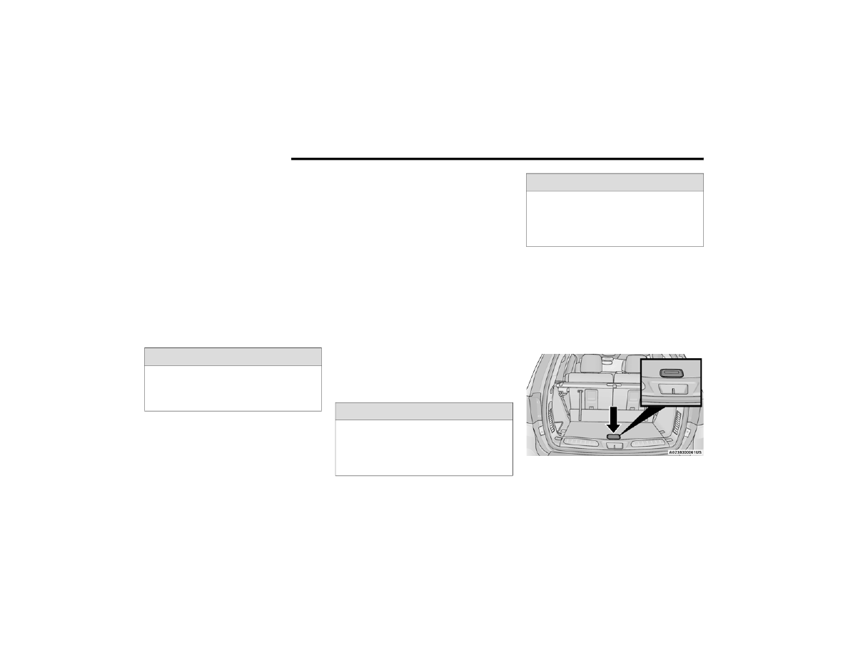
There is a removable storage bin located on the 

left side of the rear cargo area.
Additional storage can be found in the load floor. 

To access the lower storage, lift the handle and 

raise the storage lid.

Load Floor Handle

WARNING!

During power operation, personal injury or cargo 

damage may occur. Ensure the liftgate travel 

path is clear. Make sure the liftgate is closed 

and latched before driving away.

WARNING!

Driving with the liftgate open can allow 

poisonous exhaust gases into your vehicle. 

You and your passengers could be injured by 

these fumes. Keep the liftgate closed when 

you are operating the vehicle.

If you are required to drive with the liftgate 

open, make sure that all windows are closed, 

and the climate control blower switch is set at 

high speed. Do not use the recirculation 

mode.

WARNING!

GETTING TO KNOW YOUR VEHICLE

75

(Continued)

Retractable Cargo Area Cover —

If Equipped 

The purpose of this cover is for privacy, not to 

secure loads. It will not prevent cargo from shifting 

or protect passengers from loose cargo.
To cover the cargo area:
1. Grab the cover at the center handle, and pull 

it over the cargo area.

2. Insert the pins on the ends of the cover into the 

slots in the pillar trim cover.

3. The liftgate may be opened with the cargo 

cover in place.

Cargo Tie-Down Hooks 

The cargo tie-downs, located on the cargo area 

floor, should be used to safely secure loads when 

the vehicle is moving.

Tie-Down Hooks

WARNING!

In a collision, a loose cargo cover in the vehicle 

could cause injury. It could fly around in a 

sudden stop and strike someone in the vehicle. 

Do not store the cargo cover on the cargo floor 

or in the passenger compartment. Remove the 

cover from the vehicle when taken from its 

mounting. Do not store it in the vehicle.

WARNING!

Cargo tie-downs are not safe anchors for a 

child seat tether strap. In a sudden stop or 

accident, a tie-down could pull loose and allow 

the child seat to come loose. A child could be 

badly injured. Use only the anchors provided 

for child seat tethers.

To help protect against personal injury, 

passengers should not be seated in the rear 

cargo area. The rear cargo space is intended 

for load carrying purposes only, not for 

passengers, who should sit in seats and use 

seat belts.

The weight and position of cargo and 

passengers can change the vehicle center of 

gravity and vehicle handling. To avoid loss of 

control resulting in personal injury, follow these 

guidelines for loading your vehicle:

Do not carry loads that exceed the load limits 

described on the label attached to the left 

door or left door center pillar.

Always place cargo evenly on the cargo floor. 

Put heavier objects as low and as far forward 

as possible.

Place as much cargo as possible in front of the 

rear axle. Too much weight or improperly 

placed weight over or behind the rear axle can 

cause the vehicle to sway.

Do not pile luggage or cargo higher than the 

top of the seatback. This could impair visibility 

or become a dangerous projectile in a sudden 

stop or accident.

WARNING!

2

76

GETTING TO KNOW YOUR VEHICLE


ROOF LUGGAGE RACK — IF EQUIPPED  

The crossbars and side rails are designed to carry 

weight on vehicles equipped with a luggage rack. 

The load must not exceed 150 lb (68 kg), and 

should be uniformly distributed over the luggage 

rack crossbars.
The crossbars on your vehicle are delivered stowed 

within the roof rack side rails. Crossbars should 

always be used whenever cargo is placed on the 

roof rack. Check the straps frequently to be sure 

that the load remains securely attached.

Roof Rack

The roof rack does not increase the total load 

carrying capacity of the vehicle. Be sure the total 

load of cargo inside the vehicle plus that on the 

external rack does not exceed the maximum 

vehicle load capacity.

D

EPLOYING

 T

HE

 C

ROSSBARS

1. Starting with one crossbar, completely loosen 

the thumb screws at both ends of the 

crossbar.

Thumb Screw

NOTE:

The thumb screws cannot be fully removed.

2. Remove the crossbar from the stowed position 

by sliding the crossbar towards the center of 

the roof. Repeat with the crossbar on the 

opposite side.

Removing Crossbars

1 — Side Rail
2 — Crossbar

CAUTION!

Use care when removing and handling the 

crossbars to prevent damage to the vehicle.

GETTING TO KNOW YOUR VEHICLE

77

3. Starting with one crossbar, bend down the 

pivot supports at each end.

Bending Pivot

4. Position the crossbars across the roof making 

sure the letters on the crossbars align with the 

matching letters on the side rail.

Positioning Crossbars

5. Slide the crossbar into the deploy position by 

moving it towards the matching letter in the 

side rail. Be sure the crossbar is fully deployed 

with the crossbar pushed as far into the slot as 

possible. Once the crossbar is in place, tighten 

both thumb screws completely.

Installing Crossbars

6. Deploy and tighten the second crossbar to 

complete the deployment of the crossbars.

Deployed Crossbars

S

TOWING

 T

HE

 C

ROSSBARS

1. Starting with one crossbar, completely loosen 

the thumb screws at both ends. Slide the 

crossbar away from the matching letter to 

remove it from the deployed position. 

Repeat with the other crossbar.

CAUTION!

Use care when removing and handling the 

crossbars to prevent damage to the vehicle.

2

78

GETTING TO KNOW YOUR VEHICLE


2. Starting with the one crossbar, bend up the 

pivot supports at each end.

Crossbar Pivot

3. Position the crossbar along the correct side 

rail. Make sure the letters on the crossbar 

align with the matching letters on the side rail.

Stowing Crossbars

4. Slide the crossbar outward, away from the 

center of the roof. The crossbar will nest fully 

within the side rail.

Crossbar To Side Rail

5. Once the driver’s side crossbar is in place, 

tighten the thumb screws completely.

Tightening Crossbar

6. Repeat the procedure to stow the second 

crossbar on the opposite side.

Stowed Crossbars

NOTE:

To help control wind noise, stow the crossbars in 

the side rails when they are not in use.

If any metallic object is placed over the satellite 

radio antenna (if equipped), you may experience 

interruption of satellite radio reception.

WARNING!

Cargo must be securely tied down before driving 

your vehicle. Improperly secured loads can fly off 

the vehicle, particularly at high speeds, resulting 

in personal injury or property damage. Follow 

the roof rack cautions when carrying cargo on 

your roof rack.

GETTING TO KNOW YOUR VEHICLE

79

(Continued)

(Continued)

CAUTION!

To prevent damage to the roof of your vehicle, 

DO NOT carry any loads on the roof rack 

without the crossbars deployed. The load 

should be secured and placed on top of the 

crossbars, not directly on the roof. If it is 

necessary to place the load on the roof, place 

a blanket or other protective layer between 

the load and the roof surface.

To avoid damage to the roof rack and vehicle, 

do not exceed the maximum roof rack load 

capacity of 150 lb (68 kg). Always distribute 

heavy loads as evenly as possible and secure 

the load appropriately.

Load should always be secured to crossbars 

first, with tie down loops used as additional 

securing points if needed. Tie loops are 

intended as supplementary tie down points 

only. Do not use ratcheting mechanisms with 

the tie loops. Check the straps and thumb 

wheels frequently to be sure that the load 

remains securely attached.

Long loads that extend over the windshield, 

such as wood panels or surfboards, or loads 

with large frontal area should be secured to 

both the front and rear of the vehicle.

CAUTION!

Travel at reduced speeds and turn corners 

carefully when carrying large or heavy loads 

on the roof rack. Wind forces, due to natural 

causes or nearby truck traffic, can add sudden 

upward lift to a load. This is especially true on 

large flat loads and may result in damage to 

the cargo or your vehicle.

CAUTION!

2

80  

GETTING TO KNOW YOUR INSTRUMENT PANEL

INSTRUMENT CLUSTER 

GETTING TO KNOW YOUR INSTRUMENT PANEL

81

I

NSTRUMENT

 C

LUSTER

 D

ESCRIPTIONS

1. Tachometer

Indicates the engine speed in revolutions 

per minute (RPM x 1000).

2. Speedometer

Indicates vehicle speed.

3. Temperature Gauge

The temperature gauge shows engine 

coolant temperature. Any reading within the 

normal range indicates that the engine 

cooling system is operating satisfactorily.

The pointer will likely indicate a higher 

temperature when driving in hot weather, 

up mountain grades, or when towing a 

trailer. It should not be allowed to exceed 

the upper limits of the normal operating 

range.

4. Instrument Cluster Display

The instrument cluster display features a 

driver interactive display  

Ú

page 81.

5. Fuel Gauge

The pointer shows the level of fuel in the 

fuel tank when the Keyless Push Button 

Ignition is in the ON/RUN position.

 The fuel pump symbol points to 

the side of the vehicle where the 

fuel door is located  

Ú

page 137.

NOTE:

The hard telltales will illuminate for a bulb check 

when the ignition is first cycled.

INSTRUMENT CLUSTER DISPLAY

Your vehicle is equipped with an instrument cluster 

display, which offers useful information to the 

driver. With the ignition in the OFF mode, opening/

closing of a door will activate the display for 

viewing, and display the total miles, or kilometers, 

in the odometer. Your instrument cluster display is 

designed to display important information about 

your vehicle’s systems and features. Using a driver 

interactive display located on the instrument 

panel, your instrument cluster display can show 

how systems are working and give you warnings 

when they are not. The steering wheel mounted 

controls allow you to scroll through the main 

menus and submenus. You can access the specific 

information you want and make selections and 

adjustments.

WARNING!

A hot engine cooling system is dangerous. You or 

others could be badly burned by steam or boiling 

coolant. You may want to call an authorized 

dealer for service if your vehicle overheats  

Ú

page 272.

CAUTION!

Driving with a hot engine cooling system could 

damage your vehicle. If the temperature gauge 

reads “H” pull over and stop the vehicle. Idle the 

vehicle with the air conditioner turned off until 

the pointer drops back into the normal range. If 

the pointer remains on the “H”, turn the engine 

off immediately and call an authorized dealer for 

service.

3

82

GETTING TO KNOW YOUR INSTRUMENT PANEL


L

OCATION

 A

ND

 C

ONTROLS

The instrument cluster display is located in the 

center of the instrument cluster.

Instrument Cluster Display/Controls Location

The system allows the driver to select information 

by pushing the following buttons mounted on the 

steering wheel:

Instrument Cluster Display Control Buttons

Left Arrow Button 
Push the left  arrow button to return to

the main menu from an info screen or submenu 

item.

Up Arrow Button 
Push and release the up  arrow button to 

scroll upward through the main menu.

Right Arrow Button 
Push and release the right  arrow button to 

access the information screens or submenu 

screens of a main menu item.

Down Arrow Button 
Push and release the down  arrow button to 

scroll downward through the main menu.

OK Button 
Push the OK button to access/select the infor

-

mation screens or submenu screens of a main 

menu item. Push and hold the OK button for one 

second to reset displayed/selected features 

that can be reset.

1 – Instrument Cluster Display Controls
2 – Instrument Cluster Display Screen

1 — Left Arrow Button
2 — Up Arrow Button
3 — Right Arrow Button
4 — Down Arrow Button
5 — OK Button

GETTING TO KNOW YOUR INSTRUMENT PANEL

83

The instrument cluster display is located in the 

center portion of the cluster and consist of multiple 

sections:

Main Screen — The inner ring of the display will 

illuminate in gray under normal conditions, 

yellow for non critical warnings, red for critical 

warnings, and white for on demand information.

Submenu Dots — Whenever there are 

submenus available, the position within the 

submenus is shown here.

Reconfigurable Telltales/Information

Gear Selector Status (PRND)

Driver Interactive Display (Compass, Temp, 

Range to Empty, Trip A, Trip B, Average Fuel 

Economy, Current Fuel Economy, Time, Trailer 

Trip and Gain)

All Wheel Drive (AWD) Status — If Equipped

The instrument cluster display will normally display 

the main menu or the screens of a selected feature 

of the main menu. The main display area also 

displays pop-up messages that consist possible 

warning or information messages. These pop-up 

messages fall into several categories:

Five Second Stored Messages 
When the appropriate conditions occur, this 

type of message takes control of the main 

display area for five seconds and then returns to 

the previous screen. Most of the messages of 

this type are then stored (as long as the condi

-

tion that activated it remains active) and can be 

reviewed from the “Messages” main menu item. 

Examples of this message type are “Right Front 

Turn Signal Lamp Out” and “Low Tire Pressure.”

Unstored Messages 
This message type is displayed indefinitely or 

until the condition that activated the message is 

cleared. Examples of this message type are 

“Turn Signal On” (if a turn signal is left on) and 

“Lights On” (if driver leaves the vehicle with the 

lights on).

Unstored Messages Until RUN 
These messages deal primarily with the Remote 

Start feature. This message type is displayed 

until the ignition is in the RUN state. Examples of 

this message type are “Remote Start Canceled - 

Door Ajar” and “Press Brake Pedal and Push 

Button to Start.”

Five Second Unstored Messages 
When the appropriate conditions occur, this 

type of message takes control of the main 

display area for five seconds and then returns to 

the previous screen. An example of this 

message type is “Automatic High Beams On.”

3

84

GETTING TO KNOW YOUR INSTRUMENT PANEL


E

NGINE

 O

IL

 L

IFE

 R

ESET


Oil Change Required
Your vehicle is equipped with an engine oil change 

indicator system. The “Oil Change Required” 

message will display in the instrument cluster 

display for five seconds after a single chime has 

sounded, to indicate the next scheduled oil change 

interval. The engine oil change indicator system is 

duty cycle based, which means the engine oil 

change interval may fluctuate, dependent upon 

your personal driving style.
Unless reset, this message will continue to display 

each time the ignition is placed in the ON/RUN 

position. To turn off the message temporarily, push 

and release the OK or arrow buttons. To reset the 

oil change indicator system (after performing the 

scheduled maintenance), refer to the following 

procedure.

Vehicles Equipped With Keyless Enter ‘n Go™ — 

Ignition
Use the steering wheel instrument cluster display 

controls for the following procedure(s):
1. Without pressing the brake pedal, push the 

ENGINE START/STOP button and place the 

ignition in the ON/RUN position (do not start 

the engine).

2. Push and release the down  arrow button to 

scroll downward through the main menu to 

“Vehicle Info.”

3. Push and release the right  arrow button to 

access the ”Oil Life” screen.

4. Push and hold the OK button to reset oil life.

If conditions are met, the gauge and numeric 

display will update to show 100%. If conditions 

are not met a pop-up message of “To reset oil 

life engine must be off with ignition in run” will 

be displayed (for five seconds), and the user 

will remain at the Oil Life screen.

5. Push and release the up  or down  arrow 

button to exit the submenu screen.

NOTE:

If the indicator message illuminates when you start 

the vehicle, the oil change indicator system did not 

reset. If necessary, repeat this procedure.
Secondary Method Of Resetting Engine Oil Life
1. Without pressing the brake pedal, push the 

ENGINE START/STOP button and place the 

ignition to the ON/RUN position (do not start 

the engine).

2. Fully press the accelerator pedal, slowly, three 

times within 10 seconds.

3. Without pushing the brake pedal, push the 

ENGINE START/STOP button once to return the 

ignition to the OFF position.

NOTE:

If the indicator message illuminates when you start 

the vehicle, the oil change indicator system did not 

reset. If necessary, repeat this procedure.

GETTING TO KNOW YOUR INSTRUMENT PANEL

85

D

ISPLAY

 A

ND

 M

ESSAGES

Includes the following, but not limited to:

The Reconfigurable Telltales section is divided into the white or yellow telltales area on the left, and the green or red telltales area on the right.

Front Seat Belts Unbuckled

Driver Seat Belt Unbuckled

Passenger Seat Belt Unbuckled

Traction Control Off

Washer Fluid Low

Oil Pressure Low

Oil Change Due

Fuel Low

Service Anti-lock Brake System

Service Electronic Throttle Control

Service Power Steering

Cruise Off

Cruise Ready

ACC Override

Cruise Set To XXX mph or km/h

Service Shifter

Tire Pressure Screen With Low Tire(s)

Service Tire Pressure System

Park Brake Engaged

Brake Fluid Low

Engine Temperature Hot

Lights On

Right Front Turn Signal Light Out

Right Rear Turn Signal Light Out

Left Front Turn Signal Light Out

Left Rear Turn Signal Light Out

Ignition or Accessory On

Vehicle Not In Park

Remote Start Active Push Start Button

Remote Start Canceled Fuel Low

Remote Start Canceled Door Open

Remote Start Canceled Hood Open

Remote Start Canceled Liftgate Open

Remote Start Canceled Time Expired

Remote Start Disabled Start To Reset

Service Air Bag System

Service Air Bag Warning Light

Door Open

Liftgate Open

Hood Open

Shift Not Allowed

Vehicle Speed Too High To Shift to D

Vehicle Speed is Too High to Shift to R

Vehicle Speed is Too High to Shift to P

Service Transmission

3

86

GETTING TO KNOW YOUR INSTRUMENT PANEL


I

NSTRUMENT

 C

LUSTER

 D

ISPLAY

 M

ENU


I

TEMS


The instrument cluster display can be used to view 

the main menu items for several features. Use the 
up  and down  arrow buttons to scroll through 

the driver interactive display menu options until 

the desired menu is reached.
NOTE:

Depending on the vehicle’s options, feature 

settings may vary.

Main Menu

Speedometer
Push and release the up  or down  arrow 

button until the main gauge menu icon is displayed 

in the instrument cluster display. Push and release 
the left  or right  arrow button to select the 

analog or digital type speedometer display. Push 

and release the OK button to toggle units (mph or 

km/h) of the speedometer.

Vehicle Info

Push and release the up  or down  arrow 

button until the Vehicle Info icon/title is highlighted 
in the instrument cluster display. Push the left  
or right  arrow button to scroll through the 

information submenus.

Tire Pressure Monitor System

If tire pressure is OK for all tires a vehicle icon is 

displayed with tire pressure values in each 

corner of the icon.

If one or more tires have low pressure, “Inflate 

Tire To XX” is displayed with the vehicle icon and 

the tire pressure values in each corner of the 

icon with the pressure value of the low tire are 

displayed in a different color than the other tire 

pressure value.

If the Tire Pressure system requires service, 

“Service Tire Pressure System” is displayed.

Tire Pressure is an information only function, and 

cannot be reset  

Ú

page 193.

Transmission Temperature

Displays the actual transmission temperature.

Oil Temperature

Displays the actual oil temperature.

Oil Pressure

Displays the actual oil pressure.

Oil Life

Displays the current oil life of the vehicle.

Battery Voltage

Displays the current voltage level of the battery.

Driver Assist — If Equipped

Push and release the up  or down  arrow 

button until the Driver Assist display icon/title is 

highlighted in the instrument cluster display  

Ú

page 118.

Fuel Economy

Push and release the up  or down  arrow 

button until the Fuel Economy Menu icon/title is 
highlighted. Push the left  or right  arrow 

button to scroll the submenus, one with current 

fuel economy display and one without it.

Range

Current MPG, L/100 km, or km/L

Average MPG, L/100 km, or km/L

Press the OK button to reset the average fuel 

economy

NOTE:

The Range feature is not able to be reset through 

the instrument cluster display controls.

GETTING TO KNOW YOUR INSTRUMENT PANEL

87

Trip

Push and release the up  or down  arrow 

button until the Trip icon/title is highlighted in the 

instrument cluster display, then push and release 
the left  or right  arrow button to select Trip A 

or Trip B.
The Trip A and Trip B information will display the 

following:

Distance

Average Fuel Economy

Elapsed Time

Hold the OK button to reset all the information.

Trailer Tow — If Equipped

Push and release the up  or down  arrow 

button until the Trailer Tow Menu icon/title is 

highlighted in the instrument cluster display. Push 
and release the left  or right  arrow button to 

select Trailer Trip or Trailer Brake.
Trailer Trip will display the following:

Distance

NOTE:

Press and hold the OK button to reset all the

information.

Trailer Brake will display the following:

Output

Type

Gain

Stop/Start – If Equipped

Push and release the up  or down  

arrow button on the steering wheel to 

scroll to the Stop/Start menu in the driver 

interactive display  

Ú

page 114.

Audio

Push and release the up  or down  arrow 

button until the Audio Menu icon/title is 

highlighted in the instrument cluster display. This 

menu will display the audio source information, 

including the Song name, Artist name, and audio 

source with an accompanying graphic.

Messages

Push and release the up  or down  arrow 

button until the Messages Menu item is 

highlighted. This feature shows the number of 
stored warning messages. Pushing the left  or 
right  arrow button will allow you to see what the 

stored messages are.
When no messages are present, main menu icon 

will be a closed envelope.

Screen Setup

Push and release the up  or down  arrow 

button until the Screen Setup Menu icon/title is 

highlighted in the instrument cluster display. Push 

and release the OK button to enter the submenus 

and follow the prompts on the screen as needed. 

The Screen Setup feature allows you to change 

what information is displayed in the instrument 

cluster as well as the location that information is 

displayed.
Current Gear

On

Off

Gear Display

Full

Single

Favorite Menus

Speedometer

Driver Assist 

(Show/Hide)

Stop/Start

Vehicle Info

Fuel Economy 

(Show/Hide)

Trailer Tow 

(Show/Hide)

Performance 

(Show/Hide)

Trip

(Show/Hide)

Audio

(Show/Hide)

Stored 

Messages

Screen Setup

3

88

GETTING TO KNOW YOUR INSTRUMENT PANEL


NOTE:

Menus with (show/hide) can push the OK button to 

choose whether to show or hide this menu on the 

instrument cluster display.
Defaults (Restores All Settings To Default Settings)

Restore

Cancel

B

ATTERY

 S

AVER

 O

N

/B

ATTERY

 S

AVER


M

ODE

 M

ESSAGE

 — E

LECTRICAL

 L

OAD


R

EDUCTION

 A

CTIONS

 — I

F

 E

QUIPPED


This vehicle is equipped with an Intelligent Battery 

Sensor (IBS) to perform additional monitoring of the 

electrical system and status of the vehicle battery.
In cases when the IBS detects charging system 

failure, or the vehicle battery conditions are 

deteriorating, electrical load reduction actions will 

take place to extend the driving time and distance 

of the vehicle. This is done by reducing power to or 

turning off non-essential electrical loads.
Load reduction is only active when the engine is 

running. It will display a message if there is a risk 

of battery depletion to the point where the vehicle 

may stall due to lack of electrical supply, or will not 

restart after the current drive cycle.
When load reduction is activated, the message 

“Battery Saver On” or “Battery Saver Mode” will 

appear in the instrument cluster.
These messages indicate the vehicle battery has a 

low state of charge and continues to lose electrical 

charge at a rate that the charging system cannot 

sustain.
NOTE:

The charging system is independent from load 

reduction. The charging system performs a diag

-

nostic on the charging system continuously.

If the Battery Charge Warning Light is on it may 

indicate a problem with the charging system  

Ú

page 90.

The electrical loads that may be switched off 

(if equipped), and vehicle functions which can be 

affected by load reduction:

Heated Seat/Vented Seats/Heated Wheel

Rear Defroster And Heated Mirrors

HVAC System

115 Volt AC Power Inverter System

Audio and Telematics System

Loss of the battery charge may indicate one or 

more of the following conditions:

The charging system cannot deliver enough 

electrical power to the vehicle system because 

the electrical loads are larger than the capability 

of the charging system. The charging system is 

still functioning properly.

Turning on all possible vehicle electrical loads 

(e.g. HVAC to max settings, exterior and interior 

lights, overloaded power outlets +12 Volt, 

115 Volt AC, USB ports) during certain driving 

conditions (city driving, towing, frequent stop

-

ping, etc.).

Installing options like additional lights, upfitter 

electrical accessories, audio systems, alarms 

and similar devices.

Upper Left

None

Compass

Outside Temp

Time

Range To 

Empty (RTE)

Fuel Economy 

Average

Fuel Economy 

Current

Trip A

Trip B

Trailer Trip

Gain

Upper Right

None

Compass

Outside Temp

Time

Range To 

Empty (RTE)

Fuel Economy 

Average

Fuel Economy 

Current

Trip A

Trip B

Trailer Trip

Gain

GETTING TO KNOW YOUR INSTRUMENT PANEL

89

Unusual driving cycles (short trips separated by 

long parking periods).

The vehicle was parked for an extended period 

of time (weeks, months).

The battery was recently replaced and was not 

charged completely.

The battery was discharged by an electrical load 

left on when the vehicle was parked.

The battery was used for an extended period 

with the engine not running to supply radio, 

lights, chargers, +12 Volt portable appliances 

like vacuum cleaners, game consoles and 

similar devices.

What to do when an electrical load reduction 

action message is present (“Battery Saver On” or 

“Battery Saver Mode”)
During a trip:

Reduce power to unnecessary loads if possible:

Turn off redundant lights (interior or exterior)

Check what may be plugged in to power 

outlets +12 Volt, 115 Volt AC, USB ports

Check HVAC settings (blower, temperature)

Check the audio settings (volume)

After a trip:

Check if any aftermarket equipment was 

installed (additional lights, upfitter electrical 

accessories, audio systems, alarms) and review 

specifications if any (load and Ignition Off Draw 

currents).

Evaluate the latest driving cycles (distance, 

driving time and parking time).

The vehicle should have service performed if 

the message is still present during consecutive 

trips, and if the evaluation and driving pattern of 

the vehicle did not help to identify the cause.

WARNING LIGHTS AND MESSAGES

The warning/indicator lights will illuminate in the 

instrument panel together with a dedicated 

message and/or acoustic signal when applicable. 

These indications are indicative and precautionary 

and as such must not be considered as exhaustive 

and/or alternative to the information contained in 

the Owner’s Manual, which you are advised to 

read carefully in all cases. Always refer to the 

information in this chapter in the event of a failure 

indication. All active telltales will display first if 

applicable. The system check menu may appear 

different based upon equipment options and 

current vehicle status. Some telltales are optional 

and may not appear.

R

ED

 W

ARNING

 L

IGHTS

Seat Belt Reminder Warning Light  

This warning light indicates when the 

driver or passenger seat belt is 

unbuckled. When the ignition is first 

placed in the ON/RUN or ACC/ON/RUN 

position and if the driver’s seat belt is unbuckled, 

a chime will sound and the light will turn on. When 

driving, if the driver or front passenger seat belt 

remains unbuckled, the Seat Belt Reminder Light 

will flash or remain on continuously and a chime 

will sound  

Ú

page 196.

Air Bag Warning Light  

This warning light will illuminate to 

indicate a fault with the air bag, and will 

turn on for four to eight seconds as a bulb 

check when the ignition is placed in the 

ON/RUN or ACC/ON/RUN position. This light will 

illuminate with a single chime when a fault with the 

air bag has been detected, it will stay on until the 

fault is cleared. If the light is either not on during 

startup, stays on, or turns on while driving, have 

the system inspected at an authorized dealer as 

soon as possible.

3


Content      ..     3      4      5      6     ..