Dodge Journey (2020 year). Manual in english - page 13
 

  Index      Manuals     Dodge Journey (2020 year). Manual in english


Search            copyright infringement  


Content      ..     11      12      13      14     ..


Dodge Journey (2020 year). Manual in english - page 13


200

IN CASE OF EMERGENCY


Underhood Fuses (Power Distribution 

Center) 

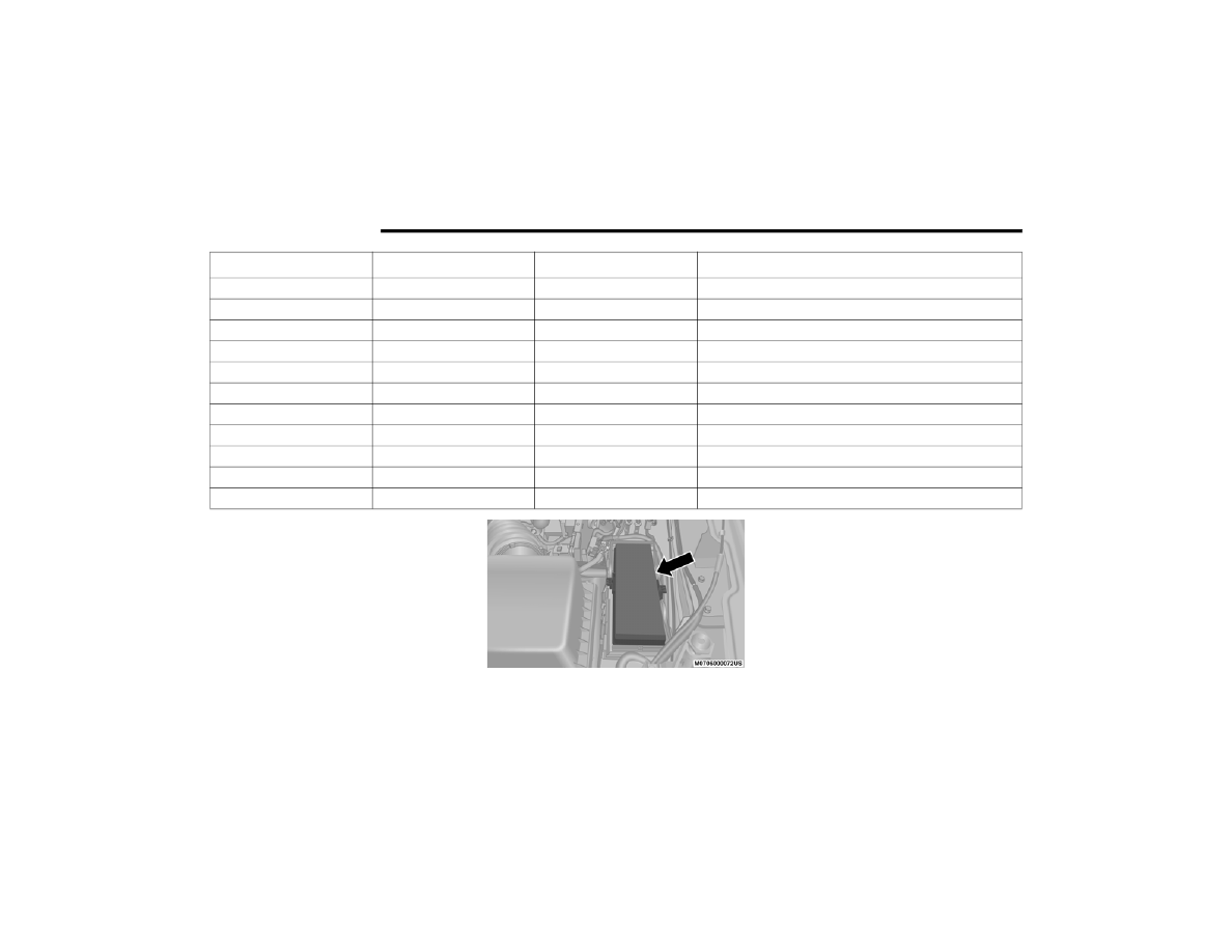
The power distribution center is located in the 

engine compartment.

Power Distribution Center

F123

25 Amp Clear

Passenger Door Module

F124

10 Amp Red

Mirrors

F125

10 Amp Red

Steering Column Control Module

F126

25 Amp Clear

Audio Amplifier

F127

20 Amp Yellow

Trailer Tow – If Equipped

F128

15 Amp Blue

Radio

F129

15 Amp Blue

Video/DVD – If Equipped

F130

15 Amp Blue

Climate Control/Instrument Panel

F131

10 Amp Red

Passenger Assistance/Hands Free System – If Equipped

F132

10 Amp Red

Tire Pressure Module

F133

10 Amp Red

Cyber Security Gateway

Cavity

Cartridge Fuse

Mini-Fuse

Description

IN CASE OF EMERGENCY

201

Cavity

Cartridge Fuse

Mini-Fuse

Description

F101

60 Amp Yellow

Interior Power Distribution Center Rail

F102

60 Amp Yellow

Interior Power Distribution Center Rail

F103

60 Amp Yellow

Interior Power Distribution Center Rail

F105

60 Amp Yellow

Interior Power Distribution Center Rail Ignition Run Relay

F106

60 Amp Yellow

Interior Power Distribution Center Rail Run/Accessory 

Relays

F139

40 Amp Green

Climate Control System Blower

F140

30 Amp Pink

Power Locks

F141

40 Amp Green

Anti-Lock Brake System

F142

40 Amp Green

Glow Plugs – If Equipped

F143

40 Amp Green

Exterior Lights 1

F144

40 Amp Green

Exterior Lights 2

F145

30 Amp Pink

To Body Computer – Lamp

F146

30 Amp Pink

Spare

F147

30 Amp Pink

Spare

F148

40 Amp Green

Radiator Fan Motor

F149

30 Amp Pink

Starter Solenoid

F150

25 Amp Clear

Powertrain Control Modules

6

202

IN CASE OF EMERGENCY


F151

30 Amp Pink

Headlamp Washer Motor – If Equipped

F152

25 Amp Clear

Diesel Fuel Heater – If Equipped

F153

20 Amp Yellow

Fuel Pump

F156

10 Amp Red

Brake/Electronic Stability Control Module

F157

10 Amp Red

Power Transfer Unit Module – If Equipped

F158

10 Amp Red

Active Hood Module – If Equipped

F159

10 Amp Red

Spare

F160

20 Amp Yellow

Interior Lights

F161

20 Amp Yellow

Horn

F162

40 Amp Red/20 Amp Lt. 

Blue

Cabin Heater #1/Vacuum Pump – If Equipped

F163

50 Amp Red

Cabin Heater #2 – If Equipped

F164

25 Amp Clear

Powertrain Auto Shutdown

F165

20 Amp Yellow

Powertrain Shutdown

F166

20 Amp Yellow

Spare

F167

30 Amp Green

Powertrain Shutdown

F168

10 Amp Red

Air Conditioner Clutch

Cavity

Cartridge Fuse

Mini-Fuse

Description

IN CASE OF EMERGENCY

203

F169

40 Amp Green

Emissions – Partial Zero Emissions Vehicle Motor

F170

15 Amp Blue

Emissions – Partial Zero Emissions Vehicle Actuators

F172

20 Amp Yellow

Spare

F173

25 Amp Clear

Anti Lock Brake Valves

F174

20 Amp Yellow

Siren – If Equipped

F175

30 Amp Green

Spare

F176

10 Amp Red

Powertrain Control Modules

F177

20 Amp Yellow

All Wheel Drive Module – If Equipped

F178

25 Amp Clear

Sunroof – If Equipped

F179

10 Amp Red

Battery Sensor

F181

100 Amp Blue

Electrohydraulic Power Steering (EHPS) – If Equipped

F182

50 Amp Red

Cabin Heater #3 – If Equipped

F184

30 Amp Pink

Front Wiper Motor

Cavity

Cartridge Fuse

Mini-Fuse

Description

6

204

IN CASE OF EMERGENCY


JACKING AND TIRE CHANGING

Jack Location

The jack and jack-handle are stowed under-

neath a cover in the rear storage bin in the 

cargo area, lift up on the handle to access the 

storage bin.

Cargo Area

The jack will be located under the storage bin, 

lift up on the storage bin cover to access the 

jack and tools.

Storage Bin

Jack/Tools Location

WARNING!

Do not attempt to change a tire on the side 

of the vehicle close to moving traffic. Pull 

far enough off the road to avoid the danger 

of being hit when operating the jack or 

changing the wheel.

Being under a jacked-up vehicle is 

dangerous. The vehicle could slip off the 

jack and fall on you. You could be crushed. 

Never put any part of your body under a 

vehicle that is on a jack. If you need to get 

under a raised vehicle, take it to a service 

center where it can be raised on a lift.

Never start or run the engine while the 

vehicle is on a jack.

The jack is designed to be used as a tool for 

changing tires only. The jack should not be 

used to lift the vehicle for service purposes. 

The vehicle should be jacked on a firm level 

surface only. Avoid ice or slippery areas.

IN CASE OF EMERGENCY

205

Spare Tire Location And Removal  

The spare tire is stowed underneath the rear of 

the vehicle and is held in place by means of a 

cable winch mechanism.

Spare Tire Location

Spare Tire Removal

NOTE:

On seven-passenger models, fold the third-row 

passenger seats flat. This will provide more 

space when accessing the jacking tools and 

when operating the winch mechanism.

1. Remove the jack-handle components 

1, 2 and 3 from storage and assemble 

them.

Lowering/Raising Spare Tire

Winch Drive Nut

NOTE:

Assemble components 2 and 3 by seating the 

small ball at the end of component 2 in the 

small hole at the end of component 3. This will 

lock these components together. Assemble 

components 1 and 2 so that the wheel nut 

socket at the end of component 1 faces upward 

when seated on component 2. This will make it 

easier to rotate the assembly when operating 

the winch mechanism.

Lowering The Spare Tire

1 — Component 1
2 — Component 2
3 — Component 3

6

206

IN CASE OF EMERGENCY


2. Fit the assembled jack-handle over the 

winch drive nut located in the jack storage 

area. Rotate the jack-handle assembly 

counterclockwise until the spare tire is on 

the ground with enough cable slack to allow 

you to pull the spare tire out from under-

neath the vehicle.

3. Pull the spare tire out from underneath the 

vehicle and raise it upright so the tire's 

tread is on the ground.

4. Tilt the retainer at the end of the winch 

cable and remove it from the center of the 

wheel.

Spare Tire Retainer

Preparations For Jacking

1. Park the vehicle on a firm, level surface as 

far from the edge of the roadway as 

possible. Avoid icy or slippery areas.

2. Turn on the Hazard Warning Flashers.

3. Apply the parking brake.

4. Place the gear selector in PARK (automatic 

transmission) or in GEAR (manual transmis-

sion).

5. Turn OFF the ignition.

6. Block both the front and rear of the wheel 

diagonally opposite the jacking position. For 

example, if the driver’s front wheel is being 

changed, block the passenger’s rear wheel.

NOTE:

Passengers should not remain in the vehicle 

when the vehicle is being raised or lifted.

CAUTION!

The winch mechanism is designed for use 

with the jack wrench extension tool only. Use 

of air wrench or power tool may damage the 

winch.

WARNING!

Do not attempt to change a tire on the side of 

the vehicle close to moving traffic. Pull far 

enough off the road to avoid being hit when 

operating the jack or changing the wheel.

IN CASE OF EMERGENCY

207

(Continued)

Jacking Instructions  

Jack Warning Label

Jacking Locations

1. Remove the spare tire, jack, and 

jack-handle from stowage.

2. Loosen, but do not remove, the wheel nuts 

on the wheel with the flat tire. Turn the 

wheel nuts counterclockwise one turn while 

the wheel is still on the ground.

WARNING!

Carefully follow these tire changing warnings 

to help prevent personal injury or damage to 

your vehicle:

Always park on a firm, level surface as far 

from the edge of the roadway as possible 

before raising the vehicle.

Turn on the Hazard Warning Flashers.

Apply the parking brake firmly and set the 

transmission in PARK.

Block the wheel diagonally opposite the 

wheel to be raised.

Never start or run the engine with the 

vehicle on a jack.

Do not let anyone sit in the vehicle when it 

is on a jack.

Do not get under the vehicle when it is on a 

jack. If you need to get under a raised 

vehicle, take it to a service center where it 

can be raised on a lift.

Only use the jack in the positions indicated 

and for lifting this vehicle during a tire 

change.

If working on or near a roadway, be 

extremely careful of motor traffic.

To assure that spare tires, flat or inflated, 

are securely stowed, spares must be 

stowed with the valve stem facing the 

ground.

WARNING!

 (Continued)

CAUTION!

Do not attempt to raise the vehicle by jacking 

on locations other than those indicated in the 

Jacking Instructions for this vehicle.

6

208

IN CASE OF EMERGENCY


3. Place the jack in the notches underneath 

the lift area that is closest to the flat tire. 

Center the jack saddle between the drain 

flute formations on the sill flange. Turn the 

jack screw clockwise to firmly engage the 

jack saddle with the lift area of the sill 

flange.

Front Lifting Point

Front Jacking Location

Rear Lifting Point

Rear Jacking Location

4. Raise the vehicle by turning the jack screw 

clockwise with the jack handle. Raise the 

vehicle until the tire just clears the road 

surface and enough clearance is obtained 

to install the spare tire. Minimum tire lift 

provides maximum stability.

WARNING!

Raising the vehicle higher than necessary can 

make the vehicle less stable. It could slip off 

the jack and hurt someone near it. Raise the 

vehicle only enough to remove the tire.

IN CASE OF EMERGENCY

209

5. Remove the wheel nuts. If equipped with 

wheel covers, remove the wheel cover from 

the wheel by hand. Do not pry the wheel 

cover off. Then, pull the wheel off the hub.

6. Mount the spare tire.

Mounting Spare Tire

NOTE:

For vehicles so equipped, do not attempt 

to install a center cap or wheel cover on 

the compact spare.

Refer to “Compact Spare Tire” and to 

“Limited Use Spare” under “Tires” in 

“Servicing And Maintenance” for addi-

tional warnings, cautions, and information 

about the spare tire, its use, and opera-

tion.

7. Install the wheel nuts with the cone-shaped 

end of the nut toward the wheel. Lightly 

tighten the wheel nuts.

8. Lower the vehicle by turning the jack screw 

counterclockwise with the jack handle.

9. Finish tightening the lug nuts. Push down on 

the wrench while at the end of the handle 

for increased leverage. Tighten the lug nuts 

in a star pattern until each nut has been 

tightened twice. For the correct lug nut 

torque, refer to “Wheel And Tire Torque 

Specifications” in “Technical Specifica-

tions”. If in doubt about the correct tight-

ness, have them checked with a torque 

wrench by an authorized dealer or service 

station.

10. Lower the jack to its fully closed position.

WARNING!

To avoid possible personal injury, handle the 

wheel covers with care to avoid contact with 

any sharp edges.

CAUTION!

Be sure to mount the spare tire with the valve 

stem facing outward. The vehicle could be 

damaged if the spare tire is mounted 

incorrectly.

WARNING!

To avoid the risk of forcing the vehicle off the 

jack, do not tighten the wheel nuts fully until 

the vehicle has been lowered. Failure to 

follow this warning may result in serious 

injury.

6

210

IN CASE OF EMERGENCY


11. Place the deflated (flat) tire in the cargo 

area. Do not stow the deflated tire in the 

spare tire stowage location. Have the 

deflated (flat) tire repaired or replaced as 

soon as possible.

12. To stow the winch cable and retainer, fit the 

assembled jack-handle over the winch drive 

nut. Rotate the jack-handle assembly clock-

wise until you hear the winch mechanism 

click three times. It cannot be over

tightened.

Stowing The Winch Cable And Retainer

13. Stow the jack-handle and jack. Remove the 

wheel blocks from the vehicle and release 

the park brake.

14. Check the tire pressure as soon as possible. 

Adjust the tire pressure as required.

Road Tire Installation

Vehicles Equipped With Wheel Covers

1. Mount the road tire on the axle.

2. To ease the installation process for steel 

wheels with wheel covers, install two lug 

nuts on the mounting studs which are on 

each side of the valve stem. Install the lug 

nuts with the cone shaped end of the nut 

toward the wheel. Lightly tighten the lug 

nuts.

Tire And Wheel Cover Or Center Cap

3. Align the valve notch in the wheel cover with 

the valve stem on the wheel. Install the 

cover by hand, snapping the cover over the 

two lug nuts. Do not use a hammer or exces-

sive force to install the cover.

4. Install the remaining lug nuts with the cone 

shaped end of the nut toward the wheel. 

Lightly tighten the lug nuts.

WARNING!

To avoid the risk of forcing the vehicle off the 

jack, do not tighten the wheel nuts fully until 

the vehicle has been lowered. Failure to 

follow this warning may result in serious 

injury.

1 — Valve Stem
2 — Valve Notch
3 — Wheel Lug Nut
4 — Wheel Cover
5 — Road Wheel

IN CASE OF EMERGENCY

211

5. Lower the vehicle to the ground by turning 

the jack handle counterclockwise.

6. Finish tightening the lug nuts. Push down on 

the wrench while at the end of the handle 

for increased leverage. Tighten the lug nuts 

in a star pattern until each nut has been 

tightened twice. For the correct lug nut 

torque, refer to “Wheel And Tire Torque 

Specifications” in “Technical Specifica-

tions”. If in doubt about the correct tight-

ness, have them checked with a torque 

wrench by an authorized dealer or service 

station.

7. After 25 miles (40 km), check the lug nut 

torque with a torque wrench to ensure that 

all lug nuts are properly seated against the 

wheel.

Vehicles Without Wheel Covers

1. Mount the road tire on the axle.

2. Install the remaining lug nuts with the cone 

shaped end of the nut toward the wheel. 

Lightly tighten the lug nuts.

3. Lower the vehicle to the ground by turning 

the jack handle counterclockwise.

4. Finish tightening the lug nuts. Push down on 

the wrench while at the end of the handle 

for increased leverage. Tighten the lug nuts 

in a star pattern until each nut has been 

tightened twice. For proper lug nut torque, 

refer to “Wheel And Tire Torque Specifica-

tions” in “Technical Specifications”. If in 

doubt about the correct tightness, have 

them checked with a torque wrench by an 

authorized dealer or service station.

5. After 25 miles (40 km), check the lug nut 

torque with a torque wrench to ensure that 

all lug nuts are properly seated against the 

wheel.

Spare Tire Stowage

NOTE:

Refer to “Spare Tire Location And Removal” in 

this section, for information on assembling the 

winch tools.

1. Place the spare tire near the winch cable. 

Hold the spare upright so that the tire's 

tread is on the ground and the valve stem 

is at the top of the wheel facing away from 

the rear of the vehicle.

2. Tilt the retainer at the end of the winch 

cable and drop it through the center of the 

wheel. Then place the spare tire with the 

cable and retainer underneath the vehicle.

WARNING!

To avoid the risk of forcing the vehicle off the 

jack, do not tighten the wheel nuts fully until 

the vehicle has been lowered. Failure to 

follow this warning may result in serious 

injury.

WARNING!

To avoid the risk of forcing the vehicle off the 

jack, do not tighten the wheel nuts fully until 

the vehicle has been lowered. Failure to 

follow this warning may result in serious 

injury.

6

212

IN CASE OF EMERGENCY


3. Fit the assembled jack-handle over the 

winch drive nut. Rotate the jack-handle 

assembly clockwise to raise the spare tire 

into the storage area. Continue to rotate the 

jack-handle assembly until you hear the 

winch mechanism click three times. It 

cannot be over tightened. Push against the 

tire several times to be sure it is held 

securely in place.

JUMP STARTING 

If your vehicle has a discharged battery, it can 

be jump started using a set of jumper cables 

and a battery in another vehicle, or by using a 

portable battery booster pack. Jump starting 

can be dangerous if done improperly, so please 

follow the procedures in this section carefully.

NOTE:

When using a portable battery booster pack, 

follow the manufacturer's operating instruc-

tions and precautions.

Preparations For Jump Start

The battery in your vehicle is located between 

the left front headlight assembly and the left 

front wheel splash shield. To allow jump 

starting, there are remote battery posts located 

on the left side of the engine compartment. The 

positive terminal has a protective cover on it, 

please remove.

Jump Starting Post

Remote Battery Posts

WARNING!

Do not attempt jump starting if the battery is 

frozen. It could rupture or explode and cause 

personal injury.

CAUTION!

Do not use a portable battery booster pack or 

any other booster source with a system 

voltage greater than 12 Volts or damage to 

the battery, starter motor, alternator or 

electrical system may occur.

(+) — Remote Positive Post
(-) — Remote Negative Post

IN CASE OF EMERGENCY

213

1. Apply the parking brake, shift the auto-

matic transmission into PARK and turn the 

ignition OFF.

2. Turn off the heater, radio, and all unneces-

sary electrical accessories.

3. Remove the protective cover over the 

remote positive (+) battery post. To remove 

the cover, push the locking tab and pull 

upward on the cover.

4. If using another vehicle to jump start the 

battery, park the vehicle within the jumper 

cable’s reach, apply the parking brake and 

make sure the ignition is OFF.

Jump Starting Procedure

Connecting The Jumper Cables

1. Connect the positive (+) end of the jumper 

cable to the remote positive (+) post of the 

discharged vehicle.

2. Connect the opposite end of the positive (+) 

jumper cable to the positive (+) post of the 

booster battery.

3. Connect the negative end (-) of the jumper 

cable to the negative (-) post of the booster 

battery.

4. Connect the opposite end of the negative (-) 

jumper cable to the remote negative (-) post 

of the vehicle with the discharged battery.

WARNING!

Take care to avoid the radiator cooling fan 

whenever the hood is raised. It can start 

anytime the ignition switch is ON. You can 

be injured by moving fan blades.

Remove any metal jewelry such as rings, 

watch bands and bracelets that could 

make an inadvertent electrical contact. You 

could be seriously injured.

Batteries contain sulfuric acid that can 

burn your skin or eyes and generate 

hydrogen gas which is flammable and 

explosive. Keep open flames or sparks 

away from the battery.

WARNING!

Do not allow vehicles to touch each other as 

this could establish a ground connection and 

personal injury could result.

WARNING!

Failure to follow this jump starting procedure 

could result in personal injury or property 

damage due to battery explosion.

CAUTION!

Failure to follow these procedures could 

result in damage to the charging system of 

the booster vehicle or the discharged vehicle.

WARNING!

Do not connect the jumper cable to the 

negative (-) post of the discharged battery. 

The resulting electrical spark could cause the 

battery to explode and could result in 

personal injury. Only use the specific ground 

point, do not use any other exposed metal 

parts.

6

214

IN CASE OF EMERGENCY


5. Start the engine in the vehicle that has the 

booster battery, let the engine idle a few 

minutes, and then start the engine in the 

vehicle with the discharged battery.

6. Once the engine is started, remove the 

jumper cables in the reverse sequence.

Disconnecting The Jumper Cables

1. Disconnect the negative (-) jumper cable 

from the remote negative (-) post of the 

vehicle with the discharged battery.

2. Disconnect the negative end (-) of the 

jumper cable from the negative (-) post of 

the booster battery.

3. Disconnect the opposite end of the positive 

(+) jumper cable from the positive (+) post 

of the booster battery.

4. Disconnect the positive (+) end of the 

jumper cable from the remote positive (+) 

post of the discharged vehicle.

5. Reinstall the protective cover over the 

remote positive (+) battery post of the 

discharged vehicle.

If frequent jump starting is required to start your 

vehicle, you should have the battery and 

charging system inspected at an authorized 

dealer.

IF YOUR ENGINE OVERHEATS 

In any of the following situations, you can 

reduce the potential for overheating by taking 

the appropriate action.

On the highways — slow down.

In city traffic — while stopped, place the trans-

mission in NEUTRAL, but do not increase the 

engine idle speed while preventing vehicle 

motion with the brakes.

NOTE:

There are steps that you can take to slow down 

an impending overheat condition: 

If your Air Conditioner (A/C) is on, turn it off. 

The A/C system adds heat to the engine 

cooling system and turning the A/C off can 

help remove this heat.

You can also turn the temperature control to 

maximum heat, the mode control to floor and 

the blower control to high. This allows the 

heater core to act as a supplement to the 

radiator and aids in removing heat from the 

engine cooling system.

CAUTION!

Accessories plugged into the vehicle power 

outlets draw power from the vehicle’s battery, 

even when not in use (i.e., cellular devices, 

etc.). Eventually, if plugged in long enough 

without engine operation, the vehicle’s 

battery will discharge sufficiently to degrade 

battery life and/or prevent the engine from 

starting.

WARNING!

You or others can be badly burned by hot 

engine coolant (antifreeze) or steam from 

your radiator. If you see or hear steam coming 

from under the hood, do not open the hood 

until the radiator has had time to cool. Never 

try to open a cooling system pressure cap 

when the radiator or coolant bottle is hot.

IN CASE OF EMERGENCY

215

2.4L Engine — If Equipped

On hot days, the engine oil temperature may 

become too hot during sustained high-speed 

driving or if towing a trailer up long grades. If 

this happens, a HOTOIL message will flash in 

the odometer and the vehicle speed will be 

reduced to 48 mph (77 km/h) maximum until 

the engine oil temperature is reduced.

NOTE:

The maximum vehicle speed is reduced to 

48 mph (77 km/h), you may reduce vehicle 

speed further as needed. Once the engine oil 

temperature is reduced, you may continue to 

drive normally.

GEAR SELECTOR OVERRIDE  

If a malfunction occurs and the gear selector 

cannot be moved out of the PARK position, you 

can use the following procedure to temporarily 

move the gear selector:

1. Turn the engine off.

2. Firmly apply the parking brake.

3. Open the center console and remove the 

gear selector override access cover (located 

in the front lower right corner of the console 

storage bin).

Gear Selector Override Access Cover

4. Press and maintain firm pressure on the 

brake pedal.

5. Insert a screwdriver or similar small tool into 

the access port, and push and hold the 

override release lever forward.

Gear Selector Override Access Cover Removal

6. Move the gear selector to the NEUTRAL 

position.

7. The vehicle may then be started in 

NEUTRAL.

8. Reinstall the gear selector override access 

cover.

CAUTION!

Driving with a hot cooling system could 

damage your vehicle. If the temperature 

gauge reads HOT (H), pull over and stop the 

vehicle. Idle the vehicle with the air 

conditioner turned off until the pointer drops 

back into the normal range. If the pointer 

remains on HOT (H), and you hear continuous 

chimes, turn the engine off immediately and 

call for service.

6


Content      ..     11      12      13      14     ..