Dodge Grand Caravan (2020 year). Manual in english - page 5
 

  Index      Manuals     Dodge Grand Caravan (2020 year). Manual in english


Search            copyright infringement  


Content      ..     3      4      5      6     ..


Dodge Grand Caravan (2020 year). Manual in english - page 5


GETTING TO KNOW YOUR VEHICLE

71

Front And Rear Overhead Consoles  

Front Overhead Console
Two versions of the overhead console are 

available. The base front overhead console 

features fixed incandescent courtesy/reading 

lights, flip-down sunglass storage and conver

-

sation mirror. The premium front overhead 

console features an LED focused light that 

illuminates the instrument panel cupholders, 

two swiveling LED lights, flip-down sunglass 

storage, conversation mirror, optional power 

sliding door switches, and an optional power 

liftgate switch.

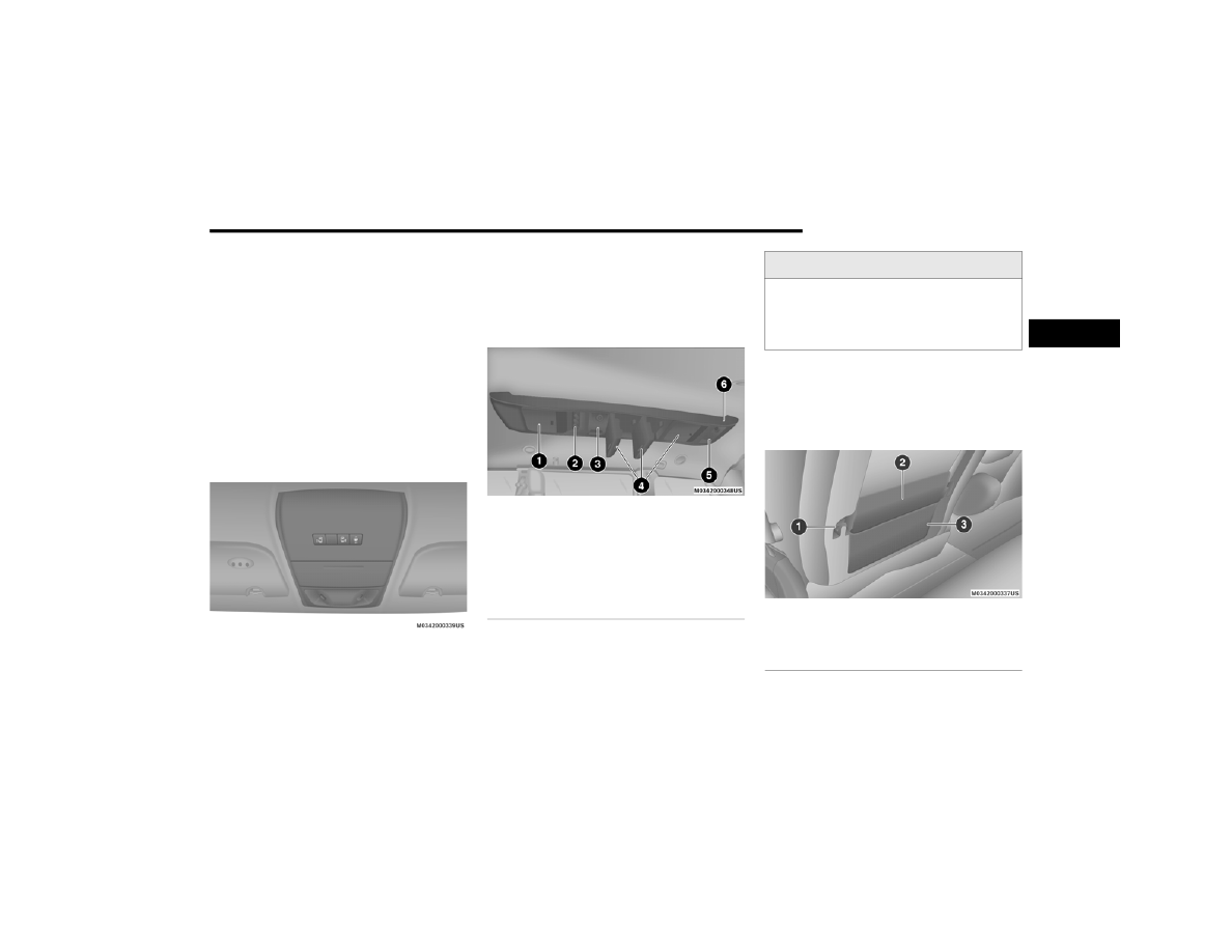
Front Overhead Console

Rear Overhead Console — If Equipped
The rear overhead storage system is available. 

There is an LED at the front of the rear console 

that shines down on the front foot-well area 

while in courtesy mode, for added convenience.

Rear Overhead Console Features

Front Door Storage

Both interior front door panels have multiple 

pockets for storage.

Driver Seatback Storage — If Equipped

The driver's seatback has a primary storage 

pocket on all models and an optional secondary 

mesh pocket.

Driver’s Seatback Storage

1 — LCD Screen
2 — Rear HVAC
3 — Interior Lights
4 — Storage
5 — Interior Lights
6 — Halo Lighting

WARNING!

If containers of hot liquid are placed in the 

bottle holder, they can spill when the door is 

closed, burning the occupants. Be careful 

when closing the doors to avoid injury.

1 — Bag Holder
2 — Standard Pocket
3 — Mesh Pocket

2

72

GETTING TO KNOW YOUR VEHICLE


(Continued)

Umbrella Holder

An umbrella holder has been conveniently 

molded into the left front door entry scuff 

molding.

Umbrella Holder

Second Row Seat Storage Bins — If Equipped

The seat storage bins are located on the floor in 

front of the second row seats. The area below 

the covers can be used for storage when the 

second row seat is in the upright position.
Pull up on the storage bin latch to open the 

cover. Slide the storage bin locking mechanism 

to the "lock" position to allow greater access to 

the storage bin.

Storage Bin

Storage Bin Safety Warning

Carefully follow these warnings to help prevent 

personal injury or damage to your vehicle:

WARNING!

In a collision, serious injury could result if the 

seat storage bin covers are not properly 

latched.

Do not drive the vehicle with the storage bin 

covers open.

Keep the storage bin covers closed and 

latched while the vehicle is in motion.

Do not operate the storage bin covers while 

the vehicle is in motion.

Do not use a storage bin latch as a tie 

down.

CAUTION!

The storage bin cover must lay flat and be 

locked to avoid damage from contact with the 

front seat tracks, which have minimal 

clearance to the cover. If the storage bin 

cover is left in the open position, front seat 

adjustment may damage the cover.

WARNING!

Always close the storage bin covers when 

your vehicle is unattended.

Do not allow children to have access to the 

second row seat storage bins. Once in the 

storage bin, young children may not be able 

to escape. If trapped in the storage bin, chil

-

dren can die from suffocation or heat 

stroke.

In a collision, serious injury could result if 

the seat storage bin covers are not properly 

latched.

GETTING TO KNOW YOUR VEHICLE

73

Seat Storage Bin Cover Emergency Release 

Lever

As a security measure, the Seat Storage Bin 

Cover has an Emergency Release Lever built 

into the latching mechanism.

Storage Bin Cover Emergency Release Lever

NOTE:

In the event of an individual being locked inside 

the storage bin, the storage bin cover can be 

opened from inside of the bin by pushing on the 

glow-in-the-dark lever attached to the storage 

bin cover latching mechanism.

Coat Hooks 

Coat hooks are located along the headliner for 

the second and third row seating positions. The 

coat hook load limit is 10 lbs (4.5 kg). Exceeding 

the recommended load limit can cause the coat 

hooks to break or disengage from the vehicle.

Cupholders 

Instrument Panel Cupholders

The instrument panel cupholders are located in 

a pull-out drawer just above the lower storage 

bin.

Front Cupholders

Pull the drawer out firmly until it stops, and 

place the container to be held in either one of 

the cupholder wells. The cupholders are 

designed to accommodate a wide variety of 

container types and sizes. Push down on the 

container to engage the cupholder retention 

features.

Do not drive the vehicle with the storage bin 

covers open. Keep the storage bin covers 

closed and latched while the vehicle is in 

motion.

Do not operate the storage bin covers while 

the vehicle is in motion.

Do not use a storage bin latch as a tie 

down.

CAUTION!

The storage bin cover must lay flat and be 

locked to avoid damage from contact with the 

front seat tracks, which have minimal 

clearance to the cover. If the storage bin 

cover is left in the open position, front seat 

adjustment may damage the cover.

WARNING!

 (Continued)

2

74

GETTING TO KNOW YOUR VEHICLE


Super Console — If Equipped

On models equipped with the Super Console, 

there are two cupholders located in the center 

of the console.

Super Console Cupholders

For rear passengers two cupholders are located 

in the pull-out drawer, located in the back of the 

Super Console. Pull the drawer out to the first 

position to use the cupholders.

Rear Cupholders

Interior Bottle Holders

There are four bottle holders located in the 

interior. One bottle holder is molded into each 

front interior door trim panels, and one bottle 

holder is molded into each side sliding interior 

door trim panel. Each holder accommodates up 

to a 20 oz (0.6 L) plastic bottle.

Interior Bottle Holder

Two outboard mesh pockets are on 

intermediate seating. The mesh pockets are 

flexible enough to hold juice boxes, toys, games 

or MP3 players, etc.

WARNING!

If containers of hot liquid are placed in the 

bottle holder, they can spill when the door is 

closed, burning the occupants. Be careful 

when closing the doors to avoid injury.

GETTING TO KNOW YOUR VEHICLE

75

Sun Screens — If Equipped

Sun screens are available for second row 

seating windows. The screens store in the sill 

trim panels, and the tops of the windows are 

equipped with hooks that the sun screens 

attach to when pulled out.

Sun Screen Retracted

Gently pull up on the tab to raise the sun screen. 

Continue pulling the sun screen until the tab is 

near the top of the window.
Once the screen is completely to the top of the 

window, extend the top bar of the sun screen 

over the two hooks attached to the top of the 

window.

Sun Screen Extended

To lower the sun screen, gently lift the tab 

upward to disengage the hooks, and feed the 

screen back into the base sill.

Electrical Power Outlets — If Equipped  

Two 12 Volt (13 Amp) power outlets are located 

on the lower instrument panel, below the open 

storage bin. The driver-side power outlet is 

controlled by the ignition switch and the 

passenger-side power outlet is connected 

directly to the battery. The driver-side power 

outlet will also operate a conventional cigar 

lighter unit (if equipped with an optional 

Smoker's Package).

Instrument Panel Power Outlets

CAUTION!

Do not exceed the maximum power of 

160 Watts (13 Amps) at 12 Volts. If the

160 Watt (13 Amp) power rating is 

exceeded the fuse protecting the system 

will need to be replaced.

Power outlets are designed for accessory 

plugs only. Do not insert any other object in 

the power outlets as this will damage the 

outlet and blow the fuse. Improper use of 

the power outlet can cause damage not 

covered by your New Vehicle Limited 

Warranty.

2

76

GETTING TO KNOW YOUR VEHICLE


One outlet in the removable floor console

(if equipped) shares a fuse with the lower outlet 

in the instrument panel and is also connected 

to the battery. Do not exceed a maximum power 

of 160 Watts (13 Amps) shared between the 

lower panel outlet and the removable floor 

console outlet.

Removable Console Power Outlet

On vehicles equipped, center console power 

outlets are located under the retractable cover. 

To access the power outlets push down on the 

cover and slide it toward the instrument panel.

Center Console Power Outlets

There is an additional 12 Volt power outlet 

located on the left rear trim panel immediately 

behind the second row left passenger seat.

Rear Panel Power Outlet

The outlet in the rear quarter panel near the 

liftgate and the upper outlet in the instrument 

panel are both controlled by the ignition switch. 

Each of these outlets can support 160 Watts 

(13 Amps). Do not exceed 160 Watts (13 Amps) 

for each of these outlets.
The power outlets include tethered caps, 

labeled with a key or battery symbol indicating 

the power source. The power outlet, located on 

the lower instrument panel, is powered directly 

from the battery. Items plugged into this power 

outlet may discharge the battery and/or prevent 

the engine from starting.

WARNING!

To avoid serious injury or death:

Only devices designed for use in this type of 

outlet should be inserted into any 12 Volt 

outlet.

Do not touch with wet hands.

Close the lid when not in use and while 

driving the vehicle.

If this outlet is mishandled, it may cause an 

electric shock and failure.

GETTING TO KNOW YOUR VEHICLE

77

Power Inverter — If Equipped

A 115 Volt, 150 Watt inverter outlet converts DC 

current to AC current, and is located on the left 

rear trim panel immediately behind the second 

row left passenger seat.

Power Inverter Outlet

The power inverter switch is located on the 

instrument panel below the climate controls.
To turn on the power outlet, push the switch 

once. Push the switch a second time to turn the 

power outlet off.
This outlet can power cellular phones, 

electronics and other low power devices 

requiring power up to 150 Watts. Certain 

high-end video game consoles exceed this 

power limit, as will most power tools.

The power inverter is designed with built-in 

overload protection. If the power rating of 

150 Watts is exceeded, the power inverter 

shuts down. Once the electrical device has 

been removed from the outlet, the inverter 

should automatically reset. If the power rating 

exceeds approximately 170 Watts, the power 

inverter may have to be reset manually. To reset 

the inverter manually push the power inverter 

button off and on. To avoid overloading the 

circuit, check the power ratings on electrical 

devices prior to using the inverter.

CAUTION!

Many accessories that can be plugged in 

draw power from the vehicle's battery, even 

when not in use (i.e., cellular phones, etc.). 

Eventually, if plugged in long enough, the 

vehicle's battery will discharge sufficiently 

to degrade battery life and/or prevent the 

engine from starting.

Accessories that draw higher power (i.e., 

coolers, vacuum cleaners, lights, etc.), will 

degrade the battery even more quickly. 

Only use these intermittently and with 

greater caution.

After the use of high power draw accesso

-

ries, or long periods of the vehicle not being 

started (with accessories still plugged in), 

the vehicle must be driven a sufficient 

length of time to allow the alternator to 

recharge the vehicle's battery.

Power outlets are designed for accessory 

plugs only. Do not hang any type of acces

-

sory or accessory bracket from the plug. 

Improper use of the power outlet can cause 

damage.

WARNING!

To avoid serious injury or death:

Do not insert any objects into the

receptacles.

Do not touch with wet hands.

Close the lid when not in use.

If this outlet is mishandled, it may cause an 

electric shock and failure.

2

78

GETTING TO KNOW YOUR VEHICLE


Smoker's Package Kit — If Equipped 

With the optional authorized dealer installed 

Smoker's Package Kit, a removable ash 

receiver is inserted into one of the two 

cupholders in the center front instrument panel. 

To install the ash receiver, align the receiver so 

the thumb grip on the lid is facing rearward. 

Push the ash receiver into either of the cup 

wells to secure. Pull upward on the ash receiver 

to remove for cleaning and/or storage.
The left rear trim panel cupholder is designed to 

accommodate a second ash receiver, if desired.

Sunglass Storage Bin — If Equipped

At the front of the overhead console, a 

compartment is provided for the storage of two 

pairs of sunglasses.
From the closed position, push the door latch to 

open the compartment.

Over Door Latch

The door will slowly rotate to the full open 

position.

Full Open Position

From this position, the door can be fully closed 

or, by rotating upward about 3/4 of the way and 

releasing, positioned for conversation mirror 

use.

Conversation Mirror Position

NOTE:

From the “conversation mirror” position, the 

door can only be closed.

To return to the full open position, the door must 

first be closed and then opened by pushing the 

latch again to release.

GETTING TO KNOW YOUR VEHICLE

79

ROOF LUGGAGE RACK — IF EQUIPPED  

The crossbars on your vehicle are delivered 

stowed within the roof rack side rails. If adding 

cargo, deploy the crossbars. Distribute cargo 

weight evenly on the roof rack crossbars, to 

maximum of 150 lbs (68 kg). The roof rack does 

not increase the total load carrying capacity of 

the vehicle. Be sure the total load of cargo 

inside the vehicle plus that on the external rack 

does not exceed the maximum vehicle load 

capacity.

Crossbar Stowed In Side Rail

The crossbars and side rails are designed to 

carry weight on vehicles equipped with a 

luggage rack. The load must not exceed 150 lbs 

(68 kg), and should be uniformly distributed 

over the luggage rack crossbars.

NOTE:

Crossbars are error-proofed and cannot be 

deployed or stowed in the incorrect positions.

To help control wind noise, stow the cross

-

bars in the side rails when they are not in use.

Deploying The Crossbars

To deploy the crossbars, completely loosen the 

thumb screws at both ends of the crossbar and 

lift the crossbar from its stowed position in the 

side rail. Repeat with crossbar on the opposite 

side.

Loosening Crossbars

Bend the crossbar supports at each end, taking 

care to keep hand clear of pivoting joint. Slide 

the thumb screw down.

Stowed Position

Deployed Position

Then, position the crossbars across the roof.

CAUTION!

Use care when removing and handling the 

crossbars to prevent damage to the vehicle.

2

80

GETTING TO KNOW YOUR VEHICLE


NOTE:

The crossbars are identical and can be placed 

in any two of the three deploy positions.

Deploy Positions – Choose Two Of Three

Make sure the directional arrows on the 

crossbars align with the directional arrows on 

the side rails. Set the crossbars into the 

deployed positions.

Crossbar To Side Rail Installation

Once the crossbars are set into position, tighten 

the thumb screws completely.

Tightening Crossbar

Stowing The Crossbars

Reverse the procedure to stow the crossbars, 

again, taking care to keep hand clear of pivoting 

joint. Crossbars are identical and can be stowed 

in either rail nest. Once the crossbars are 

stowed, tighten the thumb screws completely.

NOTE:

Load should always be secured to crossbars 

first, with rail tie down loops used as additional 

securing points if needed. Tie loops are 

intended as supplementary tie down points 

only. Do not use ratcheting mechanisms with 

the tie loops. 

Rail Tie Loops

GETTING TO KNOW YOUR VEHICLE

81

(Continued)

(Continued)

WARNING!

Cargo must be securely tied down before 

driving your vehicle. Improperly secured loads 

can fly off the vehicle, particularly at high 

speeds, resulting in personal injury or 

property damage. Follow the roof rack 

cautions when carrying cargo on your roof 

rack.

CAUTION!

To prevent damage to the roof of your 

vehicle, DO NOT carry any loads on the roof 

rack without the crossbars deployed. The 

load should be secured and placed on top 

of the crossbars, not directly on the roof. If 

it is necessary to place the load on the roof, 

place a blanket or other protective layer 

between the load and the roof surface.

To avoid damage to the roof rack and 

vehicle, do not exceed the maximum roof 

rack load capacity of 150 lb (68 kg). Always 

distribute heavy loads as evenly as possible 

and secure the load appropriately.

Load should always be secured to cross 

bars first, with tie down loops used as addi

-

tional securing points if needed. Tie loops 

are intended as supplementary tie down 

points only. Do not use ratcheting mecha

-

nisms with the tie loops. Check the straps 

and thumb wheels frequently to be sure 

that the load remains securely attached.

CAUTION!

 (Continued)

Long loads that extend over the windshield, 

such as wood panels or surfboards, or 

loads with large frontal area should be 

secured to both the front and rear of the 

vehicle.

Travel at reduced speeds and turn corners 

carefully when carrying large or heavy loads 

on the roof rack. Wind forces, due to 

natural causes or nearby truck traffic, can 

add sudden upward lift to a load. This is 

especially true on large flat loads and may 

result in damage to the cargo or your 

vehicle.

CAUTION!

 (Continued)

2

82  

GETTING TO KNOW YOUR INSTRUMENT PANEL

INSTRUMENT CLUSTER 

Base Instrument Cluster

GETTING TO KNOW YOUR INSTRUMENT PANEL

83

Premium Instrument Cluster

3

84

GETTING TO KNOW YOUR INSTRUMENT PANEL


Instrument Cluster Descriptions 

1. Tachometer

Indicates the engine speed in revolutions 

per minute (RPM x 1000).

2. Instrument Cluster Display— If Equipped / 

Odometer Display / Trip Odometer Display

Instrument Cluster Display— If Equipped

The  instrument  cluster  display  features  a

driver interactive display that is located in the

instrument  cluster.  Refer  to  “Instrument

Cluster  Display”  in  this  section  for  further

information.

Odometer Display / Trip Odometer 

Display

The  odometer  display  shows  the  total

distance the vehicle has been driven.

This also displays Trip A and Trip B, DTE, MPG

or L/100km, Outside Air Temperature (OAT)

information  to  Base  Cluster,  use  STEP  and

RESET button (on steering wheel) to access

or reset the display.

Message Display Area (Base Instrument 

Cluster)

When  the  appropriate  conditions  exist,  the

following odometer messages will display:
door — Door Ajar
gATE — Liftgate Ajar
LoW tirE — Low Tire Pressure
gASCAP — Fuel Cap Fault
noFUSE — Fuse Fault
CHAngE OIL — Oil Change Required
LoCOOL — Low Coolant

3. Speedometer

Indicates vehicle speed.

4. Fuel Gauge

The gauge shows the level of fuel in the 

fuel tank when the ignition switch is in 

the ON/RUN position.

 The fuel pump symbol points 

to the side of the vehicle where 

the fuel door is located.

5. Temperature Gauge

The temperature gauge shows engine 

coolant temperature. Any reading within 

the normal range indicates that the 

engine cooling system is operating 

satisfactorily.

The gauge can indicate a higher 

temperature when driving in hot weather 

or up mountain grades. It should not be 

allowed to exceed the upper limits of the 

normal operating range.

GETTING TO KNOW YOUR INSTRUMENT PANEL

85

NOTE:

The hard telltales will illuminate for a bulb check 

when the ignition is first cycled.

INSTRUMENT CLUSTER DISPLAY 

Your vehicle is equipped with an instrument 

cluster display, which offers useful information 

to the driver. With the ignition in the OFF 

position (and the key removed, for vehicles with 

mechanical key), opening/closing of a door will 

activate the display for viewing, and display the 

total miles or kilometers in the odometer. Your 

instrument cluster display is designed to display 

important information about your vehicle’s 

systems and features. Using a driver interactive 

display located on the instrument panel, your 

instrument cluster display can show you how 

systems are working and give you warnings 

when they are not. The steering wheel mounted 

controls allow you to scroll through and enter 

the main menus and submenus. You can 

access the specific information you want and 

make selections and adjustments.

Instrument Cluster Display Location And 

Controls 

The vehicle’s instrument cluster is equipped 

with an instrument cluster display, which offers 

useful information to the driver. With the 

ignition in the OFF position, opening/closing of 

a door will activate the instrument cluster 

display for viewing, and display the total miles 

or kilometers in the odometer.

Instrument Cluster Display

WARNING!

Driving with a hot engine cooling system 

could damage your vehicle. If the 

temperature gauge reaches “H” pull over and 

stop the vehicle. Idle the vehicle with the air 

conditioner turned off until the gauge drops 

back into the normal range and is no longer 

red. If the gauge remains on the “H”, turn the 

engine off immediately and call an authorized 

dealer for service.

WARNING!

A hot engine cooling system is dangerous. 

You or others could be badly burned by steam 

or boiling coolant. You may want to call an 

authorized dealer for service if your vehicle 

overheats. If you decide to look under the 

hood yourself, see “Servicing And 

Maintenance”.

1 – Instrument Cluster Display Controls
2 – Instrument Cluster Display Screen

3

86

GETTING TO KNOW YOUR INSTRUMENT PANEL


The instrument cluster display menu items 

consists of the following:

Fuel Economy

Vehicle Speed

Trip Info

Tire Pressure

Vehicle Info

Messages

Units

System Setup (Personal Settings)

Turn Menu Off

The system allows the driver to select 

information by pushing the following buttons 

mounted on the steering wheel:

Instrument Cluster Display Steering Wheel Buttons

Up Button 

Push and release the up button to

scroll  upward  through  the  main

menu  items  (Fuel  Economy,

Vehicle  Info,  Tire  PSI,  Cruise,

Messages, Units, System Setup).

Down Button 

Push and release the down button

to  scroll  downward  through  the

main menu items.

Right Button 

The  right  button  allows  access  to

information  in  instrument  cluster

display  submenus,  selects  some

feature  settings,  and resets some

instrument  cluster  display  features.  The

instrument cluster display prompts the driver

when  the  right  button  can  be  used  by

displaying the right arrow graphic.
Once the right button has been selected for

the desired  submenu  list,  follow the instru

-

ment  cluster  display  prompts  to  properly

select  the  desired  submenu  instrument

cluster display features.

BACK Button 

Push and release the BACK button

to scroll back to a previous menu or

submenu.


Content      ..     3      4      5      6     ..