Dodge Charger (2019 year). Manual - part 20
CAUTION!
• When installing the power distribution center cover,
it is important to ensure the cover is properly posi-
tioned and fully latched. Failure to do so may allow
water to get into the power distribution center and
possibly result in an electrical system failure.
(Continued)
CAUTION! (Continued)
• When replacing a blown fuse, it is important to use
only a fuse having the correct amperage rating. The
use of a fuse with a rating other than indicated may
result in a dangerous electrical system overload. If a
properly rated fuse continues to blow, it indicates a
problem in the circuit that must be corrected.
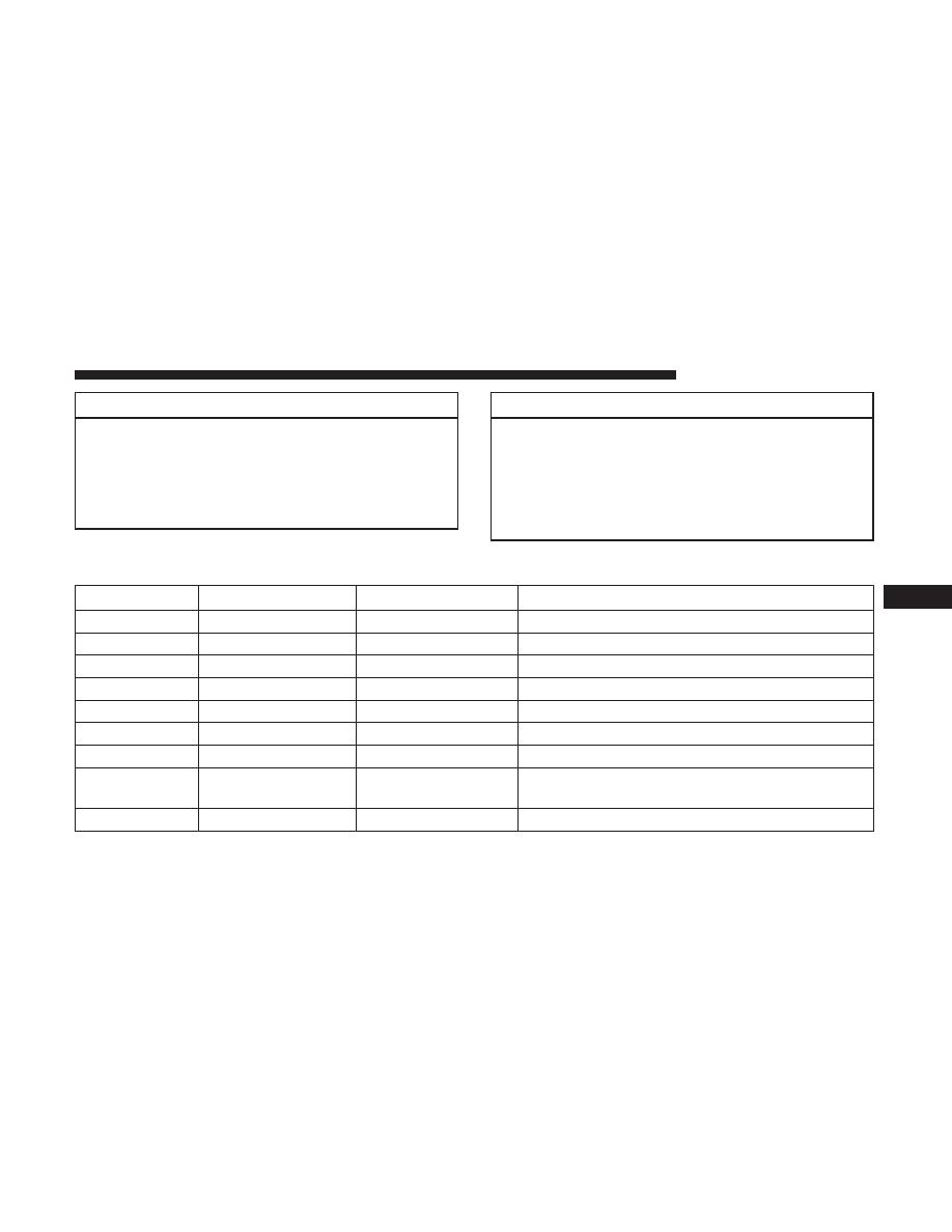
Cavity
Cartridge Fuse
Mini-Fuse
Description
1
–
–
Fuse – Spare
2
40 Amp Green
–
Radiator Fan #1 – (Non 6.2L Supercharged)
3
50 Amp Red
–
Electric Power Steering #1 – If Equipped
4
30 Amp Pink
–
Starter
5
40 Amp Green
–
Anti Lock Brake
6
30 Amp Pink
–
Anti Lock Brake
7
20 Amp Blue
–
Police Ignition Run / ACC #1
8
50 Amp Red /
20 Amp Blue
–
Radiator Fan (6.2L Supercharged) / Police Ignition
Run / ACC # 2
9
–
20 Amp Yellow
All-Wheel Drive Module – If Equipped
7
IN CASE OF EMERGENCY
317