Dodge Viper SRT-10 (ZB). Manual - part 261
110 kPa (16 psi) and will re-engage the clutch when
the high side pressure rises above 220 kPa (32 psi).
If the refrigerant pressure rises above 1654 kPa (240
psi), the PCM will actuate the cooling fan. The A/C
pressure transducer input to the PCM will also pre-
vent the A/C compressor clutch from engaging when
ambient temperatures are below about 1.0° C (50° F)
due to the pressure/temperature relationship of the
refrigerant.
The A/C pressure transducer is diagnosed using a
DRBIII
t scan tool. Refer to the appropriate diagnos-
tic information.
The A/C pressure transducer cannot be adjusted or
repaired and, if faulty or damaged, it must be
replaced.
DIAGNOSIS AND TESTING
A/C PRESSURE TRANSDUCER
The A/C pressure transducer is tested using a
DRBIII
t scan tool. Refer to the appropriate diagnos-
tic information. Before testing the A/C pressure
transducer, be certain that the transducer wire har-
ness connection is clean of corrosion and properly
connected. For the A/C to operate, an A/C pressure
transducer voltage reading between 0.451 and 4.519
volts is required. Voltages outside this range indicate
a low or high refrigerant system pressure condition
to the powertrain control module (PCM). The PCM is
programmed to respond to a low or high refrigerant
system pressure by suppressing operation of the A/C
compressor. Refer to the A/C Pressure Transducer
Voltage chart for the possible conditions indicated by
the transducer voltage reading.
A/C PRESSURE TRANSDUCER VOLTAGE
Voltage
Possible Indication
0.0
1. No sensor supply voltage
from PCM.
2. Shorted sensor circuit.
3. Faulty transducer.
0.150 TO 0.450
1. Ambient temperature below
10° C (50° F).
2. Low refrigerant system pres-
sure.
0.451 TO 4.519
1. Normal refrigerant system
pressure.
4.520 TO 4.850
1. High refrigerant system pres-
sure.
5.0
1. Open sensor circuit.
2. Faulty transducer.
REMOVAL
NOTE: Note: It is not necessary to discharge the
refrigerant system to replace the A/C pressure
transducer.
(1) Disconnect and isolate the negative battery cable.
(2) Disconnect the wire harness connector from the
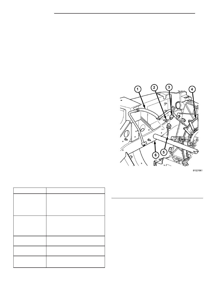
A/C pressure transducer (Fig. 14)
(3) Remove the A/C pressure transducer from the
fitting on the discharge line and remove and discard
the O-ring seal.
INSTALLATION
NOTE: Use only the specified O-ring as it is made
of special material for R-134a. Use only refrigerant
oil of the type required for the A/C compressor.
(1) Lubricate a new rubber O-ring seal with clean
refrigerant oil and install it on the A/C pressure
transducer fitting.
(2) Install the A/C pressure transducer onto the
discharge line. Tighten the A/C pressure transducer
securely.
(3) Connect the wire harness connector to the A/C
pressure transducer.
(4) Reconnect the negative battery cable.
Fig. 14 A/C Pressure Transducer
1 - DISCHARGE LINE
2 - SCREW
3 - A/C PRESSURE TRANSDUCER
4 - RADIATOR/FAN/CONDENSER MODULE
5 - WIRE HARNESS CONNECTOR
6 - LH FRAME RAIL
24 - 18
CONTROLS
ZB
A/C PRESSURE TRANSDUCER (Continued)