Dodge Viper SRT-10 (ZB). Manual - part 197


  Index      Dodge     Dodge Viper SRT-10 (ZB) - service repair manual 2005 year


Search            


Content   ..  195  196  197  198   ..


Dodge Viper SRT-10 (ZB). Manual - part 197


(22) Raise and support the vehicle.
(23) Remove the right rear tire.
(24) Remove the right rear splash shield.
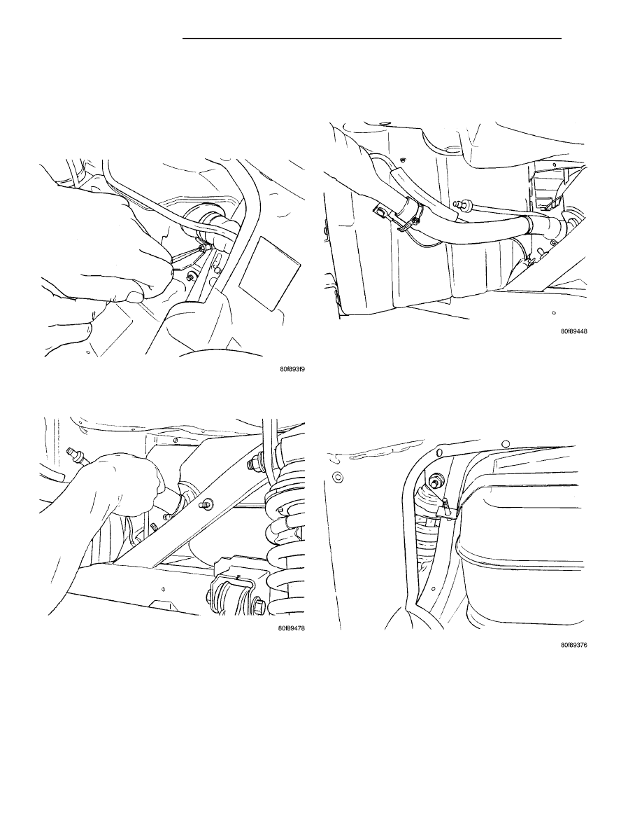
(25) Remove the fuel filler tube from fuel tank

(Fig. 47) and (Fig. 48).

(26) Disconnect the vapor line at fuel filler tube

(Fig. 49).

(27) Remove the fastener for fuel tank strap.
(28) Lower vehicle.
(29) Remove the left side fuel tank strap nut and

remove the strap (Fig. 50).

Fig. 47 FILLER NECK CLAMP

Fig. 48 FILLER TUBE REMOVAL/INSTALL

Fig. 49 FUEL FILLER TUBE VENT

Fig. 50 TANK STRAP

14 - 18

FUEL DELIVERY

ZB

FUEL TANK (Continued)

(30) Disconnect the ground strap from frame (Fig.

51).

(31) Disconnect the LDP electrical connector from

pump (Fig. 52).

(32) Remove the liquid separator (Fig. 53) from the

top of the EVAP canister.

(33) Pull wiring harness (Fig. 54) for heated back

glass down and out of the way from the top of the
fuel tank.

NOTE: You may have to trim some of the trunk
panel to make room for removal of fuel tank.

Fig. 51 GROUND STRAP

Fig. 52 FUEL TANK CONNECTORS

Fig. 53 LIQUID SEPARATOR

Fig. 54 WIRING HARNESS REMOVAL/INSTALL

ZB

FUEL DELIVERY

14 - 19

FUEL TANK (Continued)

(34) Pull fuel tank to the rear of vehicle (Fig. 55)

and disconnect the vapor lines from the top of the
fuel tank (Fig. 56).

(35) Remove the fuel tank from vehicle (Fig. 57)

and (Fig. 58).

(36) Clean vehicle.
(37) Make sure that the fuel tank heat shield (Fig.

59) and (Fig. 60) is not damaged.

Fig. 55 FUEL TANK REMOVAL/INSTALL

Fig. 56 VACUUM CONNECTION

Fig. 57 TANK REMOVAL

Fig. 58 FUEL TANK ASSEMBLY

14 - 20

FUEL DELIVERY

ZB

FUEL TANK (Continued)

INSTALLATION

(1) Make sure that the fuel tank heat shield (Fig.

59) and (Fig. 60) is not damaged.

(2) Install fuel tank half way through closeout

opening, tank may have to be pushed up from under-
neath to clear the heat shield.

(3) Install electrical wiring harness over the top of

the tank and into the hole next to the fuel pump
module hole for the heated back glass (Fig. 54).

(4) Connect the LDP electrical connector to pump

(Fig. 52).

(5) Connect the vapor lines to the tank (Fig. 55).
(6) Slide tank forward.
(7) Install the liquid separator (Fig. 53) to the top

of the EVAP canister.

(8) Install the left side fuel tank strap nut (Fig.

50).

(9) Raise vehicle and support.
(10) Install the fuel filler tube to fuel tank (Fig.

47) and (Fig. 48).

(11) Connect the vapor line at fuel filler tube (Fig.

49).

(12) Install the fastener for fuel tank strap.
(13) Install the right rear splash shield.
(14) Install the right rear tire.
(15) Lower vehicle.
(16) Install Fuel pump module into tank, refer to

the Fuel Pump module in this section.

(17) Use Special Tool #6856 to install fuel pump

module locknut (Fig. 45).

(18) Connect fuel line to the fuel pump module.

Refer to Quick-Connect Fittings in the Fuel Delivery
Section of this group.

(19) Connect fuel pump module electrical connec-

tor to fuel pump module and lock.

(20) Fill fuel tank.
(21) Connect negative battery cable.
(22) Use the DRBIII

t Scan Tool ASD Fuel System

Test to pressurize the fuel system. Check for leaks.

(23) Disconnect negative battery cable.
(24) Install the foam block to the top of the fuel

pump module (Fig. 42) and (Fig. 42).

(25) Place fuel pump module cover inplace, apply

sealer to the cover and install.

(26) Install the 4 rivets for the fuel pump module

cover (Fig. 39) and (Fig. 40).

(27) Install closeout panel in trunk, apply sealer to

the panel and install with rivets.

(28) Clean trunk area.
(29) Pull top rearward.
(30) Connect the heated back glass electrical con-

nector (Fig. 38) to both sides of the glass.

(31) Roll deck lid carpet back in place.
(32) Install the convertible top fasteners (15 nuts)

(Fig. 36) and (Fig. 37).

(33) Clean vehicle.
(34) Connect negative battery cable and install the

battery cover.

Fig. 59 FUEL TANK HEAT SHIELD

Fig. 60 FUEL TANK & HEAT SHIELD

ZB

FUEL DELIVERY

14 - 21

FUEL TANK (Continued)


Content   ..  195  196  197  198   ..