Dodge Viper SRT-10 (ZB). Manual - part 195
(15) Pull top back and install the heated back
glass electrical connector (Fig. 12)
(16) Install the convertible top fasteners (15 nuts)
(Fig. 10) and (Fig. 11).
(17) Connect negative battery cable. Install the
battery cover.
FUEL RAIL
OPERATION
The fuel system operates at approximately 379 kPa
(55 psi).
The intake manifold assembly contains a tubalur
fuel rail for the injectors. Check fuel system pressure
at the test port at the front of the fuel rail on the
passenger side.
REMOVAL
(1) Release fuel system pressure. Refer to Fuel
Pressure Release Procedure in this section.
(2) Remove the battery cover and disconnect nega-
tive battery cable.
(3) Remove the air cleaner assembly, refer to the
Engine/Air Intake System/Air Cleaner Housing for
more information.
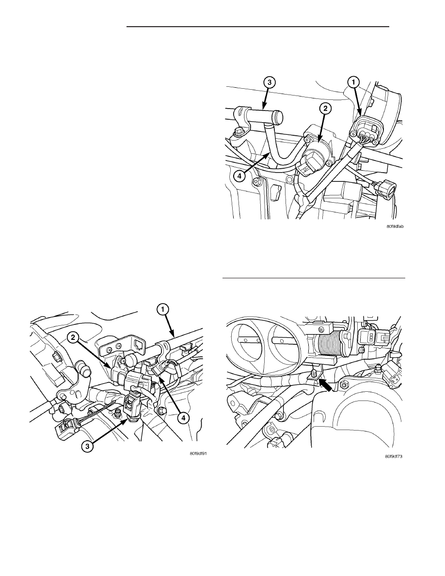
(4) Disconnect the electrical connector to the MAP
sensor and Coolant Temperature sensor (Fig. 19).
(5) Disconnect the electrical connector to the TPS
and Idle Air Control (Fig. 20).
(6) Remove the wiring harness from the wiring
clips under the throttle body (Fig. 21).
Fig. 19 MAP & COOLANT TEMP. SENSOR
Fig. 20 TPS & IDLE AIR CONTROL
1 - Throttle Position Sensor
2 - Idle Air Control Motor
3 - Fuel Rail
4 - Connector Fuel Line for Fuel Rails
Fig. 21 WIRING CLIP
14 - 10
FUEL DELIVERY
ZB
FUEL PUMP MODULE (Continued)