Dodge Viper SRT-10 (ZB). Manual - part 66


  Index      Dodge     Dodge Viper SRT-10 (ZB) - service repair manual 2005 year


Search            


Content   ..  64  65  66  67   ..


Dodge Viper SRT-10 (ZB). Manual - part 66


RELAY TEST

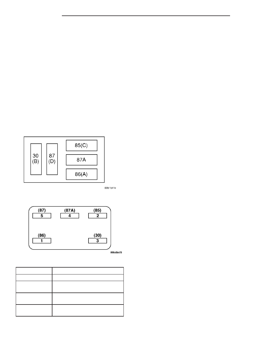
The starter relay is located in the Power Distribu-

tion Center (PDC) in the engine compartment. Refer
to the PDC label for relay identification and location.

Remove

the

starter

relay

from

the

PDC

as

described in this group to perform the following tests:

(1) A relay in the de-energized position should

have continuity between terminals 87A and 30, and
no continuity between terminals 87 and 30. If OK, go
to Step 2. If not OK, replace the faulty relay.

(2) Resistance between terminals 85 and 86 (elec-

tromagnet) should be 75 ±5 ohms. If OK, go to Step
3. If not OK, replace the faulty relay.

(3) Connect a battery B+ lead to terminals 86 and

a ground lead to terminal 85 to energize the relay.
The relay should click. Also test for continuity
between terminals 30 and 87, and no continuity
between terminals 87A and 30. If OK, refer to Relay
Circuit Test procedure. If not OK, replace the faulty
relay.

CAV

FUNCTION

30

B (+)

85

P/N POSITION SW.SENSE
(AUTO)

86

IGNITION SWITCH OUT-
PUT

87

STARTER RELAY OUT-
PUT

RELAY CIRCUIT TEST

(1) The relay common feed terminal cavity (30) is

connected to battery voltage and should be hot at all
times. If OK, go to Step 2. If not OK, repair the open
circuit to the PDC fuse as required.

(2) The relay normally closed terminal (87A) is

connected to terminal 30 in the de-energized position,
but is not used for this application. Go to Step 3.

(3) The relay normally open terminal (87) is con-

nected to the common feed terminal (30) in the ener-
gized position. This terminal supplies battery voltage
to the starter solenoid field coils. There should be
continuity between the cavity for relay terminal 87
and the starter solenoid terminal at all times. If OK,
go to Step 4. If not OK, repair the open circuit to the
starter solenoid as required.

(4) The coil battery terminal (86) is connected to

the electromagnet in the relay. It is energized when
the ignition switch is held in the ON position after
depressing the clutch pedal. Check for battery volt-
age at the cavity for relay terminal 86 with the igni-
tion switch in the ON position and push the start
button after depressing the clutch pedal. If OK, go to
Step 5. If not OK, check for an open or short circuit
to the ignition switch and repair, if required. If the
circuit to the ignition switch is OK, see the Ignition
Switch Test procedure in this group.

(5) The coil ground terminal (85) is connected to

the electromagnet in the relay. It is grounded
through the PCM. Check for continuity between the
PCM and cavity for relay terminal 85.

SAFETY SWITCHES

If

diagnostics

of

the

Clutch

Interlock/Upstop

Switch, refer to Diagnosis and Testing in the Clutch
section.

IGNITION SWITCH

After testing starter solenoid and relay, test igni-

tion switch and wiring. Refer to the Ignition Section
or Wiring Diagrams for more information. Check all
wiring for opens or shorts, and all connectors for
being loose or corroded.

STARTER BUTTON

Check starter button and wiring. Refer to the Igni-

tion Section or Wiring Diagrams for more informa-
tion. Check all wiring for opens or shorts, and all
connectors for being loose or corroded.

BATTERY

For battery diagnosis and testing, refer to the Bat-

tery section for procedures.

ALL RELATED WIRING AND CONNECTORS

Refer to Wiring Diagrams for more information.

Starter Relay Pinout

Starter Relay Pinout

8F - 22

STARTING

ZB

STARTING (Continued)

DIAGNOSIS AND TESTING - FEED CIRCUIT
RESISTANCE TEST

Before proceeding with this operation, review Diag-

nostic Preparation and Starter Feed Circuit Tests.
The following operation will require a voltmeter,
accurate to 1/10 of a volt.

CAUTION: Ignition and Fuel systems must be dis-
abled to prevent engine start while performing the
following tests.

(1) To disable the Ignition and Fuel systems, dis-

connect the Automatic Shutdown Relay (ASD). The
ASD relay is located in the Power Distribution Cen-
ter (PDC). Refer to the PDC cover for proper relay
location.

(2) Gain access to battery terminals.
(3) With all wiring harnesses and components

properly connected, perform the following:

(a) Connect the negative lead of the voltmeter to

the battery negative post, and positive lead to the
battery negative cable clamp. Rotate and hold the
ignition switch in the ON position after depressing
the clutch pedal. Observe the voltmeter. If voltage
is detected, correct poor contact between cable
clamp and post.

(b) Connect positive lead of the voltmeter to the

battery positive post, and negative lead to the bat-
tery positive cable clamp. Rotate and leave the
ignition switch key in the ON position push start
button after depressing the clutch pedal. Observe
the voltmeter. If voltage is detected, correct poor
contact between the cable clamp and post.

(c) Connect negative lead of voltmeter to battery

negative terminal, and positive lead to engine
block near the battery cable attaching point.
Rotate and leave the ignition switch in the ON
position push start button after depressing the
clutch pedal. If voltage reads above 0.2 volt, correct
poor contact at ground cable attaching point. If
voltage reading is still above 0.2 volt after correct-
ing poor contacts, replace ground cable.
(4) Connect positive voltmeter lead to the starter

motor housing and the negative lead to the battery
negative terminal. Turn the ignition switch key to
the ON position after depressing the clutch pedal. If
voltage reads above 0.2 volt, correct poor starter to
engine ground.

(a) Connect the positive voltmeter lead to the

battery positive terminal, and negative lead to bat-

tery cable blade terminal on starter solenoid.
Rotate the ignition switch in the ON position after
depressing the clutch pedal. If voltage reads above
0.2 volt, correct poor contact at battery cable to
solenoid connection. If reading is still above 0.2
volt after correcting poor contacts, replace battery
positive cable.

(b) If resistance tests do not detect feed circuit

failures, replace the starter motor.

DIAGNOSIS AND TESTING - CLUTCH PEDAL
POSITION SWITCH

For electrical diagnosis (Refer to 8 - ELECTRICAL/

STARTING/STARTER MOTOR RELAY - DIAGNO-
SIS AND TESTING).

For replacement and/or adjustment of the switch,

refer

to

Clutch,

Clutch

Pedal

Position

Switch

Removal and Installation.

SPECIFICATIONS

STARTER

Engine Application

8.3L (V 10)

Power rating

2.0 Kw

Voltage

12 VOLTS

No. of Fields

4

No. of Poles

4

Brushes

4

Drive

Offset Reduction Gear

Cranking Amperage Draw
test

150 - 280 Amps.

Engine should be up to operating temperature.

Extremely heavy oil or tight engine will increase
starter amperage draw.

TORQUE

DESCRIPTION

TORQUE

Starter Battery Cable Nut

10 N·m (90 in. lbs.)

Starter Mounting Bolts

40 N·m (30 ft. lbs.)

ZB

STARTING

8F - 23

STARTING (Continued)

STARTER MOTOR

REMOVAL

(1) Disconnect the negative battery cable (Fig. 1).

(2) Raise vehicle and support (Fig. 2).

(3) Disconnect the solenoid connector.
(4) Remove the positive battery cable.
(5) Remove the upper bolt (Fig. 3).
(6) Remove the lower bolt.
(7) Remove the starter.

INSTALLATION

(1) Install the starter.
(2) Install the lower bolt.
(3) Install the upper bolt (Fig. 3).
(4) Install the positive battery cable.

(5) Connect the solenoid connector.
(6) Lower vehicle.
(7) Connect the negative battery cable (Fig. 1).

STARTER MOTOR RELAY

DESCRIPTION

The Starter Relay is an ISO (International Stan-

dards Organization) relay located in the Power Dis-
tribution Center (PDC), positioned in the left side of
the engine compartment.

OPERATION

As battery power is applied to the relay from the igni-

tion switch, battery power is applied to the starter
motor through the relay to the starter solenoid.

The starter relay ground is provided by the PCM’s

double start override output. When the clutch inter-
lock switch (clutch pedal mounted) and start button
switch contacts are closed, the PCM will supply the
ground path for the starter relay at key ON. This
will occur if the engine RPM is below 400 RPM.

STARTER SOLENOID

DESCRIPTION

The Starter Solenoid is mounted directly to the

Starter Motor.

OPERATION

The Starter Solenoid is a switching device used to

activate the high amperage starter motor circuit from
a low amperage control circuit.

Fig. 1 BATTERY CONNECTION

Fig. 2 STARTER LOCATION

Fig. 3 STARTER BOLTS

8F - 24

STARTING

ZB

HEATED SYSTEMS

TABLE OF CONTENTS

page

page

HEATED GLASS

DESCRIPTION

. . . . . . . . . . . . . . . . . . . . . . . . . . 1

OPERATION

. . . . . . . . . . . . . . . . . . . . . . . . . . . . 1

DIAGNOSIS AND TESTING

ELECTRIC BACKLIGHT (EBL) SYSTEM

. . . . . 2

REAR WINDOW DEFOGGER RELAY

DESCRIPTION

. . . . . . . . . . . . . . . . . . . . . . . . . . 2

OPERATION

. . . . . . . . . . . . . . . . . . . . . . . . . . . . 3

REMOVAL

. . . . . . . . . . . . . . . . . . . . . . . . . . . . . 3

INSTALLATION

. . . . . . . . . . . . . . . . . . . . . . . . . . 3

REAR WINDOW DEFOGGER SWITCH

DESCRIPTION

. . . . . . . . . . . . . . . . . . . . . . . . . . 4

OPERATION

. . . . . . . . . . . . . . . . . . . . . . . . . . . . 4

REAR WINDOW DEFOGGER GRID

STANDARD PROCEDURE

GRID LINE AND TERMINAL REPAIR

. . . . . . . . 4

HEATED GLASS

DESCRIPTION

CAUTION: Grid lines can be damaged or scraped
off with sharp instruments. Care should be taken in
cleaning

glass

or

removing

foreign

materials,

decals or stickers. Normal glass cleaning solvents
or hot water used with rags or toweling is recom-
mended.

The rear window defogger system, also known as

electric backlight (EBL), consists of two vertical bus
bars linked by a series of grid lines fired onto the
inside surface of the rear window (Fig. 1).

The EBL system is turned On or Off by a switch

and timing circuit, which are integral to the A/C-
heater control located at the center of the instrument
panel.

Circuit protection is provided by a fuse located in

the power distribution center (PDC).

OPERATION

The electric backlight (EBL) system is controlled

by a momentary switch (Fig. 2) located in the A/C-
heater control on the instrument panel. When the
rear window defogger switch is pressed to the On
position, the A/C-heater control energizes the rear
window defogger (EBL) relay, which then directs
fused battery current through the relay and to the
rear defogger grid lines. The grid lines heat the glass
to help clear the rear window surface of fog or frost.

An amber indicator in the rear window defogger

switch will illuminate to indicate when the EBL sys-
tem is turned on. The A/C-heater control contains the
EBL system control circuitry including the timer
logic.

NOTE: The EBL system turns off automatically after
ten minutes of initial operation. Each following acti-

vation cycle of the EBL system will last five min-
utes.

The EBL system will be automatically turned off

after an initial programmed time interval of about
ten minutes. After the initial time interval has
expired, if the rear window defogger switch is turned
on again during the same ignition cycle, the EBL sys-
tem will automatically turn off after about five min-
utes. The EBL system will automatically shut off if
the ignition switch is turned to the Off position, or it
can be turned off manually by pressing the rear win-
dow defogger switch a second time.

Repair of the rear window defogger grid lines, bus

bars, terminals or pigtail wires can be accomplished
using the Mopar Rear Window Defogger Repair Kit
(Part Number 04549275) or equivalent (Refer to 8 -

Fig. 1 Rear Window Defogger (EBL) Grid

1 - VERTICAL BUS BARS
2 - GRID LINES
3 - REAR WINDOW GLASS

ZB

HEATED SYSTEMS

8G - 1


Content   ..  64  65  66  67   ..