Dodge Viper SRT-10 (ZB). Manual - part 64
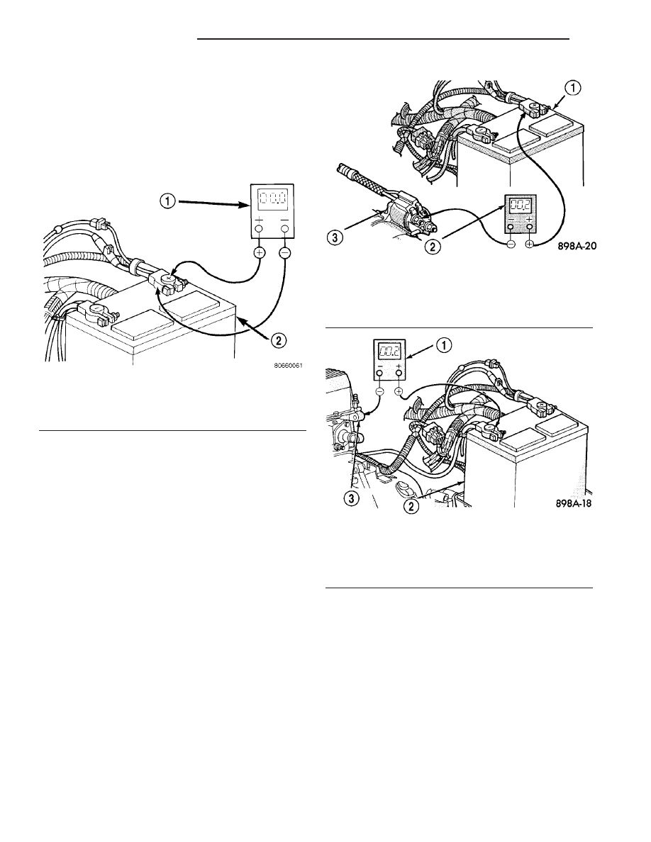
(2) Connect the positive lead of the voltmeter to
the battery positive terminal post. Connect the nega-
tive lead of the voltmeter to the battery positive cable
terminal clamp (Fig. 8). Rotate and hold the ignition
switch in the Start position. Observe the voltmeter. If
voltage is detected, correct the poor connection
between the battery positive cable terminal clamp
and the battery positive terminal post.
(3) Connect the voltmeter to measure between the
battery positive cable terminal clamp and the starter
solenoid B(+) terminal stud (Fig. 9). Rotate and hold
the ignition switch in the Start position. Observe the
voltmeter. If the reading is above 0.2 volt, clean and
tighten the battery positive cable eyelet terminal con-
nection at the starter solenoid B(+) terminal stud.
Repeat the test. If the reading is still above 0.2 volt,
replace the faulty battery positive cable.
(4) Connect the voltmeter to measure between the
battery negative cable terminal clamp and a good
clean ground on the engine block (Fig. 10). Rotate
and hold the ignition switch in the Start position.
Observe the voltmeter. If the reading is above 0.2
volt, clean and tighten the battery negative cable
eyelet terminal connection to the engine block.
Repeat the test. If the reading is still above 0.2 volt,
replace the faulty battery negative cable.
REMOVAL
(1) Turn the ignition switch to the Off position. Be
certain that all electrical accessories are turned off.
(2) Disconnect the negative and then the positive
battery cables from the battery terminals.
(3) One at a time, trace the battery cable retaining
pushpins, fasteners and routing clips until the appro-
priate cable is free from the vehicle.
(4) Remove the battery cable from the vehicle.
INSTALLATION
(1) Position the battery cable in the vehicle.
(2) One at a time, install the battery cable retain-
ing pushpins, fasteners and routing clips until the
appropriate cable is installed in the correct position
in the vehicle.
(3) Connect the positive and negative battery
cables on the battery terminals.
Fig. 8 TEST BATTERY POSITIVE CONNECTION
RESISTANCE - TYPICAL
1 - VOLTMETER
2 - BATTERY
Fig. 9 TEST BATTERY POSITIVE CABLE
RESISTANCE - TYPICAL
1 - BATTERY
2 - VOLTMETER
3 - STARTER MOTOR
Fig. 10 TEST GROUND CIRCUIT RESISTANCE -
TYPICAL
1 - VOLTMETER
2 - BATTERY
3 - ENGINE GROUND
8F - 14
BATTERY SYSTEM
ZB
BATTERY CABLES (Continued)