Dodge Viper SRT-10 (ZB). Manual - part 67
ELECTRICAL/HEATED
GLASS/REAR
WINDOW
DEFOGGER GRID - STANDARD PROCEDURE -
GRID LINE AND TERMINAL REPAIR).
DIAGNOSIS AND TESTING
ELECTRIC BACKLIGHT (EBL) SYSTEM
NOTE: Illumination of the defogger switch indicator
lamp does not necessary mean that electrical cur-
rent is reaching the rear glass heating grid lines.
NOTE: For circuit descriptions and diagrams of the
rear window defogger (EBL) system, refer to 8W -
WIRING DIAGRAM INFORMATION.
Operation of the electrical backlight (EBL) system
can be confirmed by the following:
(1) Turn the ignition switch to the On position. Set
the rear window defogger switch in the On position.
The rear window defogger operation can be checked
by feeling the surfaces of the rear window glass or
outside rear view mirror glass. A distinct difference
in temperature between the grid lines and the adja-
cent clear glass or the mirror glass should be
detected within three to four minutes of operation.
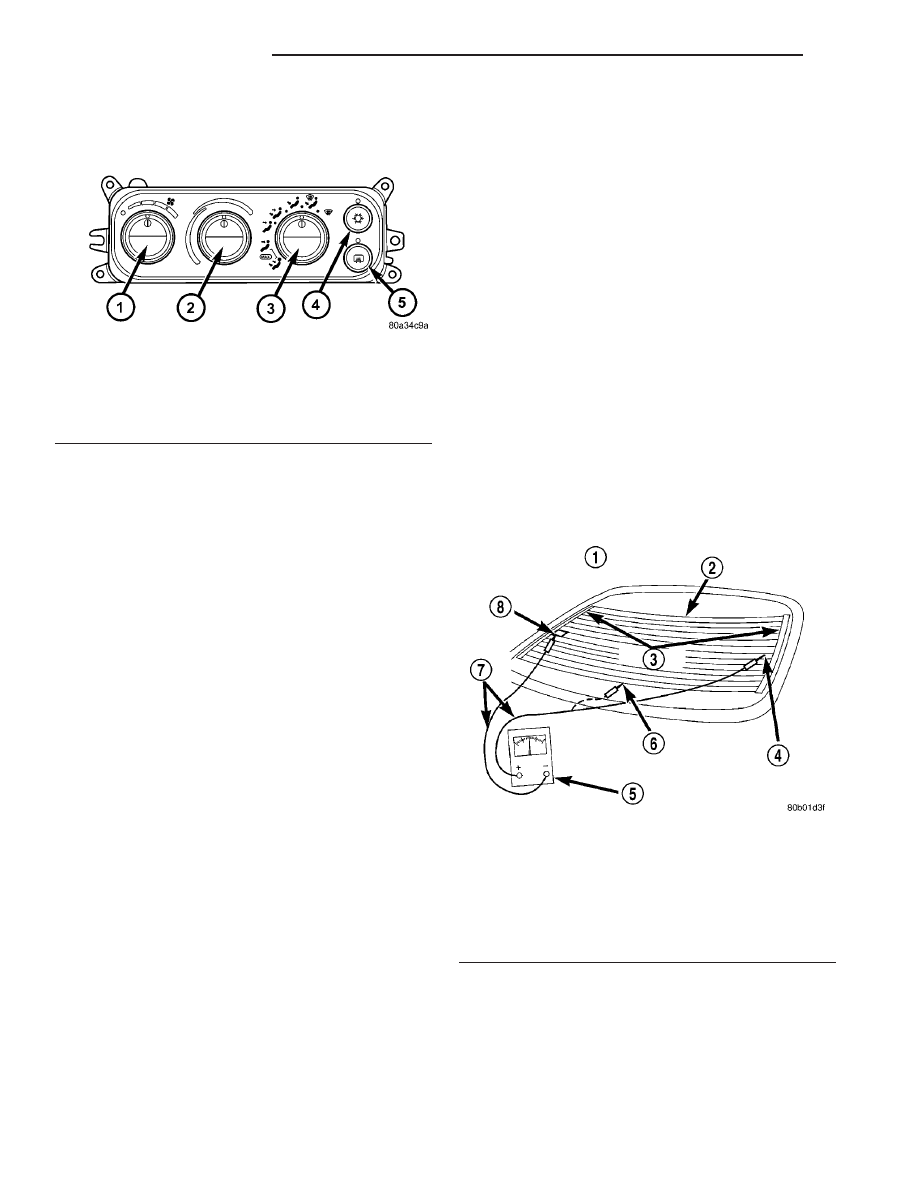
(2) If a temperature difference is not detected, use
a 12-volt DC voltmeter and contact the rear glass
heating grid power feed terminal A with the positive
lead, and the ground terminal B with the negative
lead (Fig. 3). The voltmeter should read battery volt-
age. If the voltmeter does not read battery voltage,
check the following:
• Confirm that the ignition switch is On.
• Make sure that the rear glass heating grid feed
wire and ground wire are connected to the terminals.
Confirm that the ground wire has continuity to
ground.
• Check the EBL relay and fuse located in the
power distribution center (PDC) in the engine com-
partment. The relay and fuse must be tight in their
receptacles and all electrical connections must be
secure. Refer to the appropriate wiring information
for diagnosis and testing of the ISO-standard relay.
(3) When the above steps have been completed and
the system is still inoperative, one or more of the fol-
lowing could be defective. It may be necessary to con-
nect
a
DRBIII
t scan tool to perform further
diagnostics. Refer to Body Diagnostic Procedures.
• Rear window defogger switch in the A/C-heater
control.
• Rear window defogger timing circuity in the A/C-
heater control.
• Fused ignition switch output circuit from the
body control module (BCM).
• Rear window defogger grid lines (all grid lines
would have to be broken, or the power feed or the
ground wire disconnected, for the entire heating grid
to be inoperative).
(4) If the EBL system operation has been verified
but rear window defogger LED indicator does not
illuminate, replace the A/C-heater control (Refer to
24 - HEATING & AIR CONDITIONING/CONTROLS/
A/C HEATER CONTROL - REMOVAL).
REAR WINDOW DEFOGGER
RELAY
DESCRIPTION
The rear window defogger (EBL) relay (Fig. 4) is a
International Standards Organization (ISO) micro-re-
lay. Relays conforming to the ISO specifications have
Fig. 2 Rear Window Defogger Switch
1 - BLOWER SPEED CONTROL
2 - TEMPERATURE CONTROL
3 - MODE CONTROL
4 - A/C SELECT SWITCH
5 - REAR WINDOW DEFOGGER SWITCH
Fig. 3 Grid Line Test
1 - VIEW FROM INSIDE VEHICLE
2 - HEATED WINDOW GRID
3 - BUS BARS
4 - VOLTAGE FEED (A)
5 - VOLTMETER
6 - MID-POINT (C)
7 - PICK-UP LEADS
8 - GROUND (B)
8G - 2
HEATED SYSTEMS
ZB
HEATED GLASS (Continued)