Dodge Viper SRT-10 (ZB). Manual - part 13


  Index      Dodge     Dodge Viper SRT-10 (ZB) - service repair manual 2005 year


Search            


Content   ..  11  12  13  14   ..


Dodge Viper SRT-10 (ZB). Manual - part 13


(2) Assemble

pieces

of

Remover,

Special

Tool

6969B, through bushing as shown (Fig. 46).

CAUTION: Do not use any type of impact wrench on
Special Tool 6969B. Use only hand tools.

(3) Hold Screw, Special Tool 6969-3, stationary

while rotating Nut, Special Tool 6969-4 clockwise.
This action will force isolator bushing out of control
arm, into Receiver, Special Tool 6969-2.

(4) Remove tools and bushing from arm. A small

portion of bushing rubber may come loose lodging
itself between Remover and control arm bushing
boar, causing some resistance during tool removal.

NOTE: For bushing installation, (Refer to 2 - SUS-
PENSION/FRONT/UPPER CONTROL ARM - ASSEM-
BLY).

ASSEMBLY - UPPER CONTROL ARM
(ISOLATOR BUSHINGS)

NOTE: The following procedure can be used for
either upper control arm isolator bushing.

(1) Squarely position isolator bushing into control

arm pivot end bore from outboard side.

NOTE: Before using Special Tool 6969B, lubricate
threads of Screw Assembly 6969-3 with appropriate
lubricant.

(2) Assemble

pieces

of

Remover,

Special

Tool

6969B, through bushing and arm as shown (Fig. 47).

CAUTION: Do not use any type of impact wrench on
Special Tool 6969B. Use only hand tools.

(3) Hold Screw, Special Tool 6969-3, stationary

while rotating Nut, Special Tool 6969-4 clockwise.
This action will draw isolator bushing into control
arm.

(4) Continue to rotate Nut until bushing metal

flange squarely contacts control arm. Do not over-
tighten Screw.

(5) Remove tools.
(6) Install upper control arm on vehicle. (Refer to 2

- SUSPENSION/FRONT/UPPER CONTROL ARM -
INSTALLATION)

INSTALLATION

(1) Position upper control arm in mounting brack-

ets on frame. Install mounting bolts as shown
through mounting brackets and control arm bushings
(Fig. 44). Install nuts on frame mounting bolts. DO
NOT FULLY TIGHTEN BOLTS AT THIS TIME.

(2) Install upper ball joint stud into steering

knuckle. Install ball joint castle nut (Fig. 43).
Tighten castle nut to 102 N·m (75 ft. lbs.) torque.
Once nut is tightened to specified torque, it
may be necessary to continue tightening nut a
small amount to allow for cotter pin installa-
tion through castle nut and hole in ball joint
stud. DO NOT LOOSEN NUT.

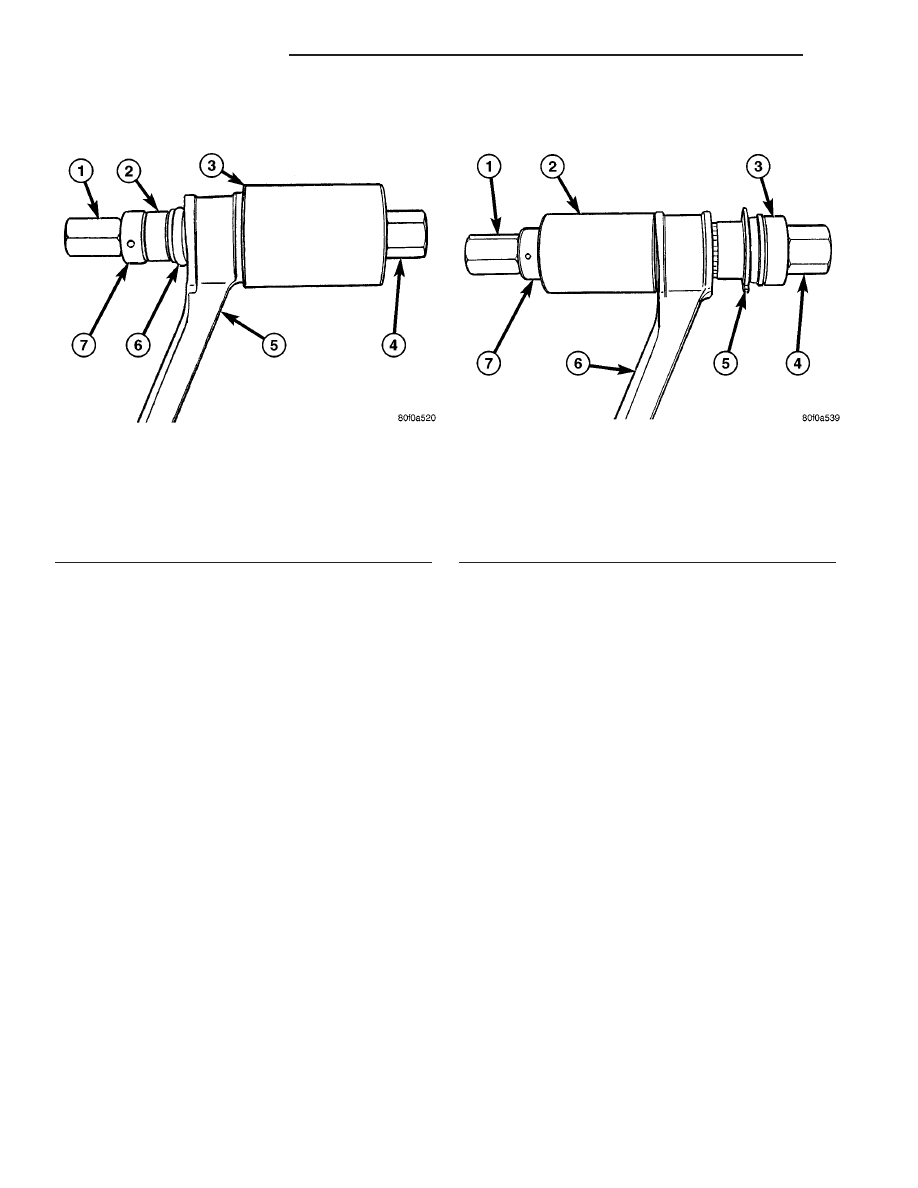
Fig. 46 Tool 6969B Installed For Bushing Removal

1 - DOUBLE THREADED NUT 6969-4
2 - SPACER 6969-1
3 - RECEIVER 6969-2
4 - SCREW ASSEMBLY 6969-3
5 - CONTROL ARM
6 - BUSHING
7 - BEARING

Fig. 47 Tool 6969B Installed For Bushing Installation

1 - DOUBLE THREADED NUT 6969-4
2 - CUP 6969-7
3 - INSTALLER 6969-8
4 - SCREW ASSEMBLY 6969-3
5 - NEW BUSHING
6 - CONTROL ARM
7 - BEARING

2 - 26

FRONT SUSPENSION

ZB

UPPER CONTROL ARM (Continued)

(3) Install cotter pin through nut and stud of

upper ball joint (Fig. 43).

(4) Install ABS wheel speed sensor in steering

knuckle (Fig. 42). Install and tighten mounting bolt
to 11 N·m (100 in. lbs.) torque.

(5) Install

brake

rotor

and

brake

caliper

on

knuckle. (Refer to 5 - BRAKES/HYDRAULIC/ME-
CHANICAL/ROTOR - INSTALLATION)

(6) Install wheel and tire assembly (Refer to 22 -

TIRES/WHEELS - INSTALLATION). Progressively
tighten wheel mounting nuts in proper sequence to
122 N·m (90 ft. lbs.) torque.

(7) Lower vehicle.

(8) Position vehicle on alignment rack/drive-on

hoist.

(9) Set vehicle to design height. (Refer to 2 - SUS-

PENSION/WHEEL

ALIGNMENT

-

STANDARD

PROCEDURE

-

DESIGN

HEIGHT

MEASURE-

MENT)

(10) Tighten upper control arm frame mounting

bolts to 102 N·m (75 ft. lbs.) torque.

(11) Perform wheel alignment. (Refer to 2 - SUS-

PENSION/WHEEL

ALIGNMENT

-

STANDARD

PROCEDURE)

(12) Road test vehicle to ensure proper operation.

ZB

FRONT SUSPENSION

2 - 27

UPPER CONTROL ARM (Continued)

REAR SUSPENSION

TABLE OF CONTENTS

page

page

REAR SUSPENSION

SPECIFICATIONS

REAR SUSPENSION FASTENER TORQUE

. . 29

SPECIAL TOOLS

REAR SUSPENSION

. . . . . . . . . . . . . . . . . . . 29

HUB / BEARING

DESCRIPTION

. . . . . . . . . . . . . . . . . . . . . . . . . 30

OPERATION

. . . . . . . . . . . . . . . . . . . . . . . . . . . 30

DIAGNOSIS AND TESTING - HUB AND

BEARING (REAR)

. . . . . . . . . . . . . . . . . . . . . 31

REMOVAL

. . . . . . . . . . . . . . . . . . . . . . . . . . . . . 31

INSTALLATION

. . . . . . . . . . . . . . . . . . . . . . . . . 33

KNUCKLE

REMOVAL

. . . . . . . . . . . . . . . . . . . . . . . . . . . . . 33

INSTALLATION

. . . . . . . . . . . . . . . . . . . . . . . . . 35

LOWER BALL JOINT

DESCRIPTION

. . . . . . . . . . . . . . . . . . . . . . . . . 35

OPERATION

. . . . . . . . . . . . . . . . . . . . . . . . . . . 36

DIAGNOSIS AND TESTING - LOWER BALL

JOINT (REAR)

. . . . . . . . . . . . . . . . . . . . . . . . 36

LOWER BALL JOINT SEAL BOOT

REMOVAL

. . . . . . . . . . . . . . . . . . . . . . . . . . . . . 36

INSTALLATION

. . . . . . . . . . . . . . . . . . . . . . . . . 36

LOWER CONTROL ARM

REMOVAL

. . . . . . . . . . . . . . . . . . . . . . . . . . . . . 37

DISASSEMBLY - ISOLATOR BUSHINGS

. . . . . . 39

INSPECTION - LOWER CONTROL ARM

. . . . . . 39

ASSEMBLY - ISOLATOR BUSHINGS

. . . . . . . . . 40

INSTALLATION

. . . . . . . . . . . . . . . . . . . . . . . . . 40

SHOCK ASSEMBLY

REMOVAL

. . . . . . . . . . . . . . . . . . . . . . . . . . . . . 41

DISASSEMBLY

. . . . . . . . . . . . . . . . . . . . . . . . . 42

ASSEMBLY

. . . . . . . . . . . . . . . . . . . . . . . . . . . . 43

INSTALLATION

. . . . . . . . . . . . . . . . . . . . . . . . . 45

STABILIZER BAR

REMOVAL

. . . . . . . . . . . . . . . . . . . . . . . . . . . . . 47

INSTALLATION

. . . . . . . . . . . . . . . . . . . . . . . . . 47

STABILIZER BAR BUSHINGS

REMOVAL

. . . . . . . . . . . . . . . . . . . . . . . . . . . . . 48

INSTALLATION

. . . . . . . . . . . . . . . . . . . . . . . . . 48

STABILIZER LINK

REMOVAL

. . . . . . . . . . . . . . . . . . . . . . . . . . . . . 48

INSTALLATION

. . . . . . . . . . . . . . . . . . . . . . . . . 49

TOE LINK

DESCRIPTION

. . . . . . . . . . . . . . . . . . . . . . . . . 49

OPERATION

. . . . . . . . . . . . . . . . . . . . . . . . . . . 49

REMOVAL

. . . . . . . . . . . . . . . . . . . . . . . . . . . . . 49

INSTALLATION

. . . . . . . . . . . . . . . . . . . . . . . . . 50

UPPER BALL JOINT

DESCRIPTION

. . . . . . . . . . . . . . . . . . . . . . . . . 51

OPERATION

. . . . . . . . . . . . . . . . . . . . . . . . . . . 51

DIAGNOSIS AND TESTING - UPPER BALL

JOINT (REAR)

. . . . . . . . . . . . . . . . . . . . . . . . 51

UPPER BALL JOINT SEAL BOOT

REMOVAL

. . . . . . . . . . . . . . . . . . . . . . . . . . . . . 52

INSTALLATION

. . . . . . . . . . . . . . . . . . . . . . . . . 52

UPPER CONTROL ARM

REMOVAL

. . . . . . . . . . . . . . . . . . . . . . . . . . . . . 52

DISASSEMBLY - ISOLATOR BUSHINGS

. . . . . . 52

INSPECTION - UPPER CONTROL ARM

. . . . . . 53

ASSEMBLY - ISOLATOR BUSHINGS

. . . . . . . . . 54

INSTALLATION

. . . . . . . . . . . . . . . . . . . . . . . . . 54

2 - 28

REAR SUSPENSION

ZB

REAR SUSPENSION

SPECIFICATIONS

REAR SUSPENSION FASTENER TORQUE

DESCRIPTION

N·m

Ft.

Lbs.

In.

Lbs.

Brake Caliper (Hydraulic)
Mounting Bolts

115

85

Hub And Bearing Mounting
Bolts

149

110

Hub Nut

258

190

Lower Ball Joint Castle Nut

160

118

Lower Control Arm Frame
Pivot (Cam) Bolts

102

75

Parking Brake Caliper
Mounting Bolt - Lower

52

38

Parking Brake Caliper
Mounting Bolt - Upper

32

24

Shock Assembly Lower
Mounting Bolt

136

100

Shock Assembly Upper
Mounting Bolt

136

100

Stabilizer Bar Bushing
Retainer Bolts

91

67

Stabilizer Link Nuts

23

17

200

Toe Link Adjuster Jam Nut

75

55

Toe Link Inboard Mounting
Bolt

75

55

Toe Link Outboard Mount-
ing Bolt Nut

75

55

Toe Link Knuckle Nut

75

55

Upper Ball Joint Castle Nut

102

75

Upper Control Arm Frame
Pivot Bolts

102

75

Wheel Mounting (Lug) Nuts

122

90

SPECIAL TOOLS

REAR SUSPENSION

Installer, Ball Joint 6761

Height Gages, Suspension 6914

Remover/Installer, Bushing 6969B

Spacer, Control Arm Removing 6983

ZB

REAR SUSPENSION

2 - 29


Content   ..  11  12  13  14   ..