Dodge Viper SRT-10 (ZB). Manual - part 10
(7) Remove bolt and nut attaching shock assembly
to bracket on lower control arm (Fig. 17).
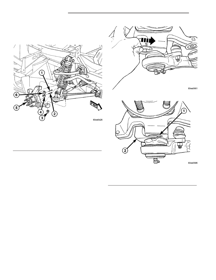
(8) Remove cotter pin and nut from lower ball joint
stud (Fig. 19).
CAUTION: Do not strike or apply heat to steering
knuckle in an effort to separate ball joint studs from
steering knuckle.
CAUTION:
Install
Spacer,
Special
Tool
6983,
between grease seal and knuckle as shown to avoid
damaging grease seal (Fig. 20).
NOTE: Use of Spacer, Special Tool 6983, is neces-
sary to allow proper use of Puller, Special Tool
C-4150A, to release lower ball joint from knuckle.
(9) Insert Spacer, Special Tool 6983, between lower
ball joint grease seal and steering knuckle (Fig. 20).
Push Spacer in until it surrounds ball joint stud.
CAUTION: When releasing ball joint from knuckle
using Puller, Special Tool C-4150A, use care not to
pinch and damage ball joint grease seal.
(10) Install Puller, Special Tool C-4150A, over
Spacer and knuckle as shown (Fig. 21). Ball bearing
in bolt of Special Tool C-4150A must be cen-
tered in end of lower ball joint stud.
(11) Release lower ball joint from knuckle using
Puller. Remove tools.
(12) Remove nuts, cam bolts and cam washers
attaching lower control arm to mounting brackets on
frame rail (Fig. 17). Slightly spread ends of mounting
brackets to ease removal of lower control arm from
brackets.
(13) Remove lower control arm.
DISASSEMBLY - LOWER CONTROL ARM
(ISOLATOR BUSHINGS)
NOTE: The following procedure can be used for
either lower control arm isolator bushing.
Fig. 19 Knuckle Mounting
1 - UPPER BALL JOINT COTTER PIN
2 - LOWER BALL JOINT COTTER PIN
3 - TIE ROD NUT
4 - LOWER BALL JOINT NUT
5 - KNUCKLE (WITH HUB AND BEARING)
6 - UPPER BALL JOINT NUT
Fig. 20 Inserting Spacer Between Knuckle And Seal
Fig. 21 Puller And Spacer Positioned To Release
Ball Joint
1 - SPACER 6983
2 - PULLER C-4150A
2 - 14
FRONT SUSPENSION
ZB
LOWER CONTROL ARM (Continued)