Dodge Viper SRT-10 (ZB). Manual - part 9


  Index      Dodge     Dodge Viper SRT-10 (ZB) - service repair manual 2005 year


Search            


Content   ..  7  8  9  10   ..


Dodge Viper SRT-10 (ZB). Manual - part 9


(5) Using hex wrench or driver socket, remove bolt

retaining ABS tone wheel to hub and bearing (Fig.
11).

(6) Remove ABS tone wheel.
(7) Remove nut securing outer tie rod to steering

knuckle.

(8) Remove outer tie rod from steering knuckle

using Puller, Special Tool C-4150A (Fig. 7).

(9) Remove four mounting bolts, then hub and

bearing assembly from steering knuckle (Fig. 4).

(10) Using an appropriate tool, remove tone wheel

seal from knuckle.

INSTALLATION

(1) Attach Installer, Special Tool 6573, to end of

Drive Handle, Special Tool C-4171 (Fig. 12).

(2) Place NEW seal on end of Installer, Special

Tool 6573.

(3) From inboard side, align seal with seal bore in

knuckle. Slowly tap tool with hammer, driving seal
into place. Stop when tool bottoms against knuckle
(Fig. 12). Remove tools.

CAUTION: A corrosion prevention gasket is used
between the hub and bearing and the steering
knuckle (Fig. 13). The gasket is required to prevent
galvanic corrosion between the hub and bearing
and the steering knuckle. The corrosion prevention

gasket must be used when installing a hub and
bearing in the steering knuckle.

(4) Install a new corrosion prevention gasket on

hub and bearing before installing it in steering
knuckle (Fig. 13).

(5) Install hub and bearing in steering knuckle.

Align holes in corrosion gasket with holes in hub and
bearing, and steering knuckle.

(6) Install four hub and bearing mounting bolts

(Fig. 4). Tighten mounting bolts to 61 N·m (45 ft.
lbs.) torque.

(7) Make sure mating surface of tone wheel and

hub and bearing is clean.

(8) Install tone wheel through seal on rear of

knuckle and against rear of hub and bearing assem-
bly (Fig. 11).

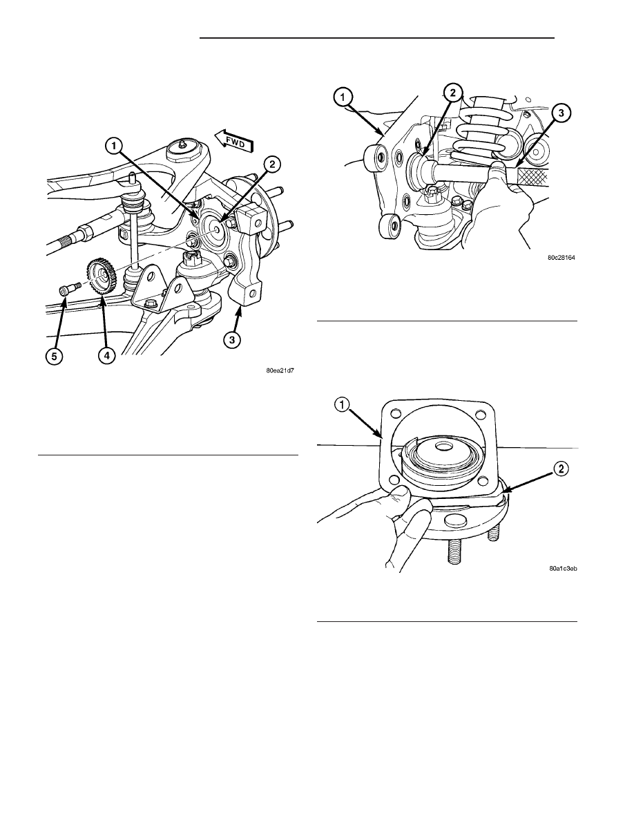
Fig. 11 Tone Wheel Mounting

1 - SEAL
2 - HUB AND BEARING
3 - KNUCKLE
4 - TONE WHEEL
5 - MOUNTING BOLT

Fig. 12 Seal Installation Using Special Tools

1 - STEERING KNUCKLE
2 - 6573
3 - C-4171

Fig. 13 Corrosion Gasket

1 - CORROSION GASKET
2 - HUB/BEARING

2 - 10

FRONT SUSPENSION

ZB

KNUCKLE/ABS TONE WHEEL SEAL (Continued)

(9) Using same bolt or identical replacement bolt,

mount tone wheel to hub and bearing. Tighten bolt to
17 N·m (13 ft. lbs.) torque.

(10) Install brake rotor, then caliper. (Refer to 5 -

BRAKES/HYDRAULIC/MECHANICAL/ROTOR

-

INSTALLATION)

(11) Install wheel speed sensor head in steering

knuckle (Fig. 10). Install mounting bolt. Tighten
mounting bolt to 11 N·m (100 in. lbs.) torque.

(12) Verify

proper

wheel

speed

sensor-to-tone

wheel air gap. (Refer to 5 - BRAKES - ABS - SPEC-
IFICATIONS)

(13) Install outer tie rod onto steering knuckle.

Install a NEW tie rod nut. Tighten tie rod nut to 75
N·m (55 ft. lbs.) torque.

(14) Install tire and wheel assembly (Refer to 22 -

TIRES/WHEELS - INSTALLATION). Progressively
tighten wheel mounting nuts in proper sequence to
122 N·m (90 ft. lbs.) torque.

(15) Lower vehicle.
(16) Road test vehicle to ensure proper operation

of base brakes and ABS.

LOWER BALL JOINT

DESCRIPTION

The lower ball joint is pressed into the lower con-

trol arm. It has a tapered stud for attachment of the
ball joint to the steering knuckle (Fig. 14). The
tapered stud of the ball joint is fastened to the steer-
ing knuckle using a castle nut and a cotter pin.

Due to the lower control arm being made of alumi-

num and the ball joint being made of steel (dissimi-
lar metals), corrosion may occur between the pieces.
For this reason, the lower ball joint has a corrosion

preventative coating applied to it. A corrosion preven-
tion gasket is also used between the ball joint and
the lower control arm (Fig. 14).

DIAGNOSIS AND TESTING - LOWER BALL
JOINT (FRONT)

Replacement is necessary if more than 0.51 mm

(0.02 in.) axial end play of the ball joint stud exists.
Refer to the following procedure to inspect the lower
ball joint for wear.

CAUTION: When raising the vehicle by the lower
control arm using a floor jack, care must be used
so control arm does not get nicked, gouged,
deformed or damaged in any other way by the floor
jack.

(1) Position floor jack under outer end of front

lower control arm. Carefully raise vehicle so front
wheel and tire assembly is just lightly contacting
floor (vehicle weight relieved from tire).

(2) Have helper grasp tire at top and apply an

inward and outward force against top of the tire.
While force is being applied against tire, look for any
movement between lower ball joint and steering
knuckle.

(3) If any lateral movement is evident at lower ball

joint, replacement is necessary.

LOWER BALL JOINT SEAL
BOOT

REMOVAL

NOTE: Review all Warnings and Cautions (Refer to
2 - SUSPENSION - WARNING)

(1) Raise vehicle. (Refer to LUBRICATION &

MAINTENANCE/HOISTING - STANDARD PROCE-
DURE)

(2) Remove wheel and tire assembly. (Refer to 22 -

TIRES/WHEELS - REMOVAL)

(3) Remove brake caliper from knuckle and hang

out of the way, then remove brake rotor. (Refer to 5 -
BRAKES/HYDRAULIC/MECHANICAL/ROTOR

-

REMOVAL)

(4) Remove bolt fastening wheel speed sensor head

to steering knuckle (Fig. 10). Remove sensor head
from knuckle.

(5) Loosen, but do not remove, nut attaching stabi-

lizer bar link to lower control arm (Fig. 17). Back off
and position nut at end of link stud (Fig. 18).

Fig. 14 Lower Ball Joint

1 - TAPERED STUD
2 - CORROSION GASKET INSTALLED HERE
3 - GREASE FITTING
4 - BALL JOINT

ZB

FRONT SUSPENSION

2 - 11

KNUCKLE/ABS TONE WHEEL SEAL (Continued)

CAUTION: The nut must be positioned at the end of
the stabilizer bar link stud to help prevent the end
of the stud from being damaged when separating it
from the lower control arm.

(6) Position center punch in dimple on end of sta-

bilizer bar link stud (Fig. 18). Strike center punch
with hammer, releasing link stud from lower control
arm. Remove nut.

(7) Remove bolt and nut attaching shock assembly

to bracket on lower control arm (Fig. 17).

(8) Remove cotter pin and nut from lower ball joint

stud (Fig. 19).

CAUTION: Do not strike or apply heat to steering
knuckle in an effort to separate ball joint studs from
steering knuckle.

CAUTION:

Install

Spacer,

Special

Tool

6983,

between grease seal and knuckle as shown to avoid
damaging grease seal (Fig. 20).

NOTE: Use of Spacer, Special Tool 6983, is neces-
sary to allow proper use of Puller, Special Tool
C-4150A, to release lower ball joint from knuckle.

(9) Insert Spacer, Special Tool 6983, between lower

ball joint grease seal and steering knuckle (Fig. 20).
Push Spacer in until it surrounds ball joint stud.

CAUTION: When releasing ball joint from knuckle
using Puller, Special Tool C-4150A, use care not to
pinch and damage ball joint grease seal.

(10) Install Puller, Special Tool C-4150A, over

Spacer and knuckle as shown (Fig. 21). Ball bearing
in bolt of Special Tool C-4150A must be cen-
tered in end of lower ball joint stud.

(11) Release lower ball joint from knuckle using

Puller. Remove tools.

(12) Move knuckle away from lower ball joint.
(13) Using a suitable cleaner, clean debris away

from seal without contaminating joint.

(14) Using a screw driver or other suitable tool,

pry seal boot off ball joint (Fig. 15).

INSTALLATION

(1) Wipe off used grease around ball joint stem.
(2) Place NEW ball joint seal boot over ball joint

stem.

(3) By hand, start seal boot bottom flange over

sides of ball joint.

(4) Position Installer, Special Tool 6761, over seal

boot aligning it with bottom flange (Fig. 16). Apply
hand pressure to the rear of Installer until seal boot

flange is pressed squarely against control arm.
Remove tool.

(5) Install lower ball joint stud into steering

knuckle. Install ball joint castle nut (Fig. 19).
Tighten castle nut to 160 N·m (118 ft. lbs.) torque.
Once nut is tightened to specified torque, it
may be necessary to continue tightening nut a
small amount to allow for cotter pin installa-
tion through castle nut and hole in ball joint
stud. DO NOT LOOSEN NUT.

(6) Install cotter pin through nut and stud of lower

ball joint (Fig. 19).

(7) Lubricate

lower

ball

joint

assembly

using

Mopar

t Multi-Mileage Lube or equivalent.

Fig. 15 Seal Boot Removal From Ball Joint

1 - BALL JOINT
2 - SCREWDRIVER
3 - LOWER CONTROL ARM
4 - SEAL BOOT

Fig. 16 Placing Special Tool Over Seal Boot

1 - INSTALLER 6761
2 - SEAL BOOT FLANGE
3 - CONTROL ARM

2 - 12

FRONT SUSPENSION

ZB

LOWER BALL JOINT SEAL BOOT (Continued)

(8) Install shock assembly into mounting bracket

on lower control arm. Install shock assembly mount-
ing bolt and nut (Fig. 17). DO NOT TIGHTEN
MOUNTING BOLT AT THIS TIME.

(9) Install stabilizer bar link into mounting hole on

lower control arm (Fig. 17). Install stabilizer bar link
nut and tighten to 23 N·m (17 ft. lbs.) torque.

(10) Install ABS wheel speed sensor in steering

knuckle (Fig. 10). Install and tighten mounting bolt
to 11 N·m (100 in. lbs.) torque.

(11) Install brake rotor and brake caliper on

knuckle. (Refer to 5 - BRAKES/HYDRAULIC/ME-
CHANICAL/ROTOR - INSTALLATION)

(12) Install wheel and tire assembly (Refer to 22 -

TIRES/WHEELS - INSTALLATION). Progressively
tighten wheel mounting nuts in proper sequence to
122 N·m (90 ft. lbs.) torque.

(13) Lower vehicle.
(14) Position vehicle on alignment rack/drive-on

hoist.

(15) Set vehicle to design height. (Refer to 2 -

SUSPENSION/WHEEL ALIGNMENT - STANDARD
PROCEDURE

-

DESIGN

HEIGHT

MEASURE-

MENT).

(16) Tighten shock assembly lower mounting bolt

to 135 N·m (100 ft. lbs.) torque.

(17) Return vehicle to curb height.

LOWER CONTROL ARM

REMOVAL

NOTE: Review all Warnings and Cautions. (Refer to
2 - SUSPENSION - WARNING).

(1) Raise vehicle. (Refer to LUBRICATION &

MAINTENANCE/HOISTING - STANDARD PROCE-
DURE).

(2) Remove wheel and tire assembly (Refer to 22 -

TIRES/WHEELS - REMOVAL).

(3) Remove brake caliper from knuckle and hang

out of the way, then remove brake rotor. (Refer to 5 -
BRAKES/HYDRAULIC/MECHANICAL/ROTOR

-

REMOVAL)

(4) Remove bolt fastening wheel speed sensor head

to steering knuckle (Fig. 10). Remove sensor head
from knuckle.

(5) Loosen, but do not remove, nut attaching stabi-

lizer bar link to lower control arm (Fig. 17). Back off
and position nut at end of link stud (Fig. 18).

CAUTION: The nut must be positioned at the end of
the stabilizer bar link stud to help prevent the end
of the stud from being damaged when separating it
from the lower control arm.

(6) Position center punch in dimple on end of sta-

bilizer bar link stud (Fig. 18). Strike center punch
with hammer, releasing link stud from lower control
arm. Remove nut.

Fig. 17 Front Suspension Mounting

1 - UPPER CONTROL ARM
2 - CAM BOLT
3 - CAM WASHER
4 - STABILIZER BAR LINK
5 - LOWER CONTROL ARM
6 - SHOCK ASSEMBLY

Fig. 18 Stabilizer Bar Link Removal

1 - STABILIZER BAR ATTACHING LINK
2 - NUT
3 - CENTER PUNCH
4 - STUD
5 - LOWER CONTROL ARM
6 - STEERING KNUCKLE

ZB

FRONT SUSPENSION

2 - 13

LOWER BALL JOINT SEAL BOOT (Continued)


Content   ..  7  8  9  10   ..