Dodge Ram Truck 1500-2500-3500. Manual - part 982
P2110-ELECTRONIC THROTTLE CONTROL - FORCED LIMITED RPM (CONTINUED)
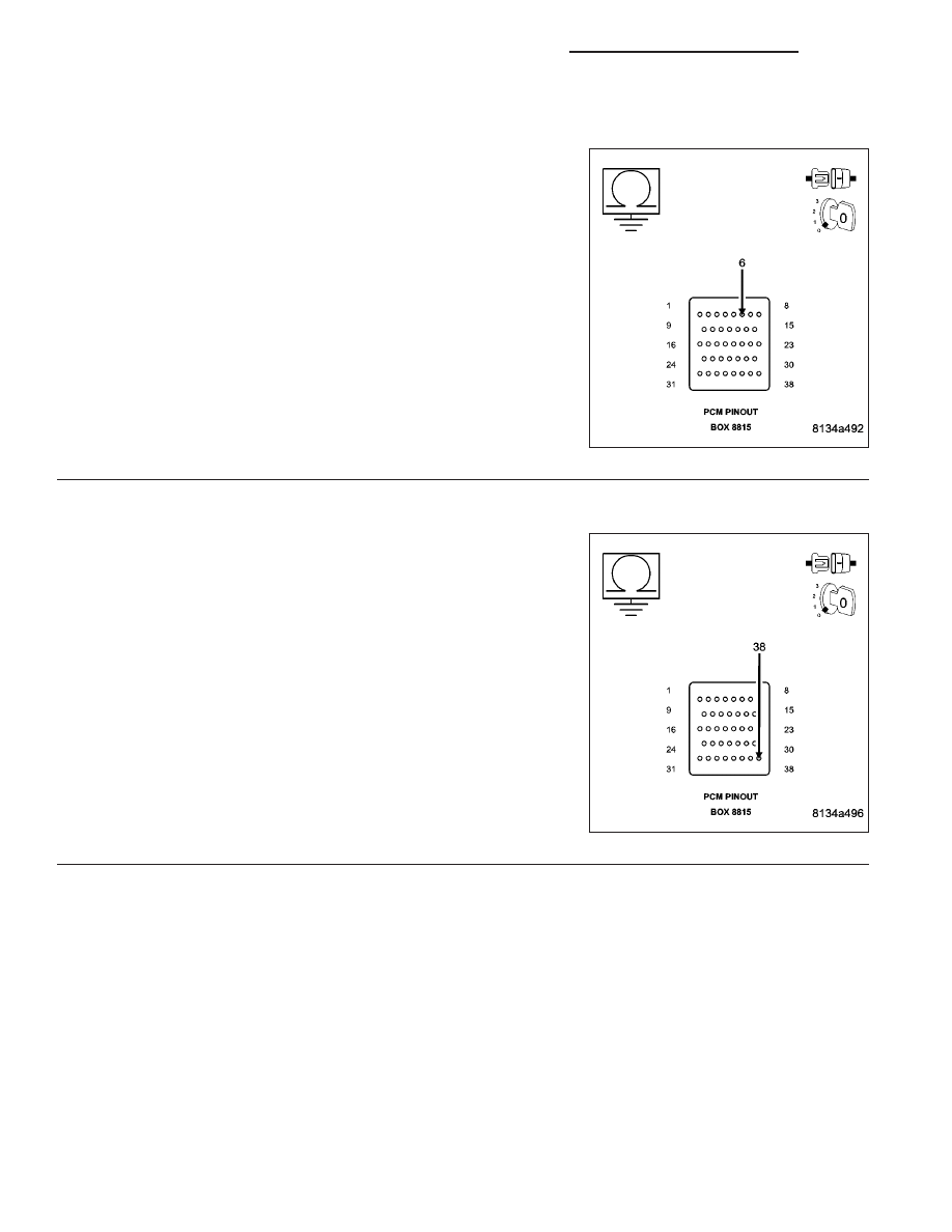
5.
(K447) ETC POSITIVE CIRCUIT SHORTED TO GROUND
Measure the resistance between a known good ground and the (K447)
ETC Positive circuit at the appropriate terminal of special tool #8815.
Is the resistance below 100 ohms?
Yes
>> Repair the short to ground in the (K447) ETC Positive cir-
cuit.
Perform the POWERTRAIN VERIFICATION TEST. (Refer
to 9 - ENGINE - STANDARD PROCEDURE)
No
>> Go To 6
6.
(K448) ETC NEGATIVE CIRCUIT SHORTED TO GROUND
Measure the resistance between a known good ground and the (K448)
ETC Negative circuit at the appropriate terminal of special tool #8815.
Is the resistance below 100 ohms?
Yes
>> Repair the short to ground in the (K448) ETC Negative cir-
cuit.
Perform the POWERTRAIN VERIFICATION TEST. (Refer
to 9 - ENGINE - STANDARD PROCEDURE)
No
>> Go To 7
9 - 850
ENGINE - ELECTRICAL DIAGNOSTICS - 3.7L/4.7L/5.7L
DR/DH