Dodge Ram Truck 1500-2500-3500. Manual - part 608
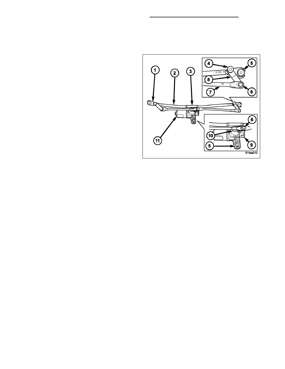
WIPER MODULE
DESCRIPTION
The wiper module is secured with screws through
three rubber grommet-type insulators (5) to the cowl
plenum panel. The module is concealed beneath the
molded plastic cowl plenum cover/grille panel between
the base of the windshield and the rear edge of the
hood panel. The ends of the pivot shafts protruding
through openings in the cowl plenum cover/grille panel
to drive the wiper arms and blades are the only visible
components of the wiper module. The wiper module
consists of the following major components:
•
Bracket - The wiper module bracket consists of a long tubular steel main member (2) that has a die cast pivot
bracket (1) at each end to which the two wiper pivots are secured. A stamped steel clamp secures the center
of the tubular member to the die cast bracket integral to the wiper motor with two screws.
•
Crank Arm (10) - The wiper motor crank arm is a stamped steel unit with a slotted hole on the driven end that
is secured to the wiper motor output shaft with a nut, and has a ball stud secured to the drive end.
•
Linkage (2) - Two stamped steel drive links connect the wiper motor crank arm to the wiper pivot lever arms.
The left side drive link has a plastic socket-type bushing (6) on each end. The right side drive link has a plastic
socket-type bushing on one end, and a plastic sleeve-type bushing on the other end. The socket-type bushing
on one end of each drive link is snap-fit over the ball stud on the lever arm (8) of its respective pivot. The right
side drive link sleeve-type bushing end is then fit over the motor crank arm ball stud, and the other socket-type
bushing of the left side drive link is snap-fit over the exposed end of the wiper motor crank arm ball stud.
•
Motor (11) - The wiper motor features an integral die cast bracket to which the wiper module bracket is
secured with a stamped steel clamp and two screws near the top and which has a single rubber insulated
mounting ear at the bottom. This die casting also serves as the wiper motor transmission housing from which
the wiper motor output shaft exits. A nut secures the wiper motor crank arm to the motor output shaft. The
two-speed permanent magnet wiper motor features an integral transmission, an internal park switch, and an
internal automatic resetting circuit breaker.
•
Pivots (2) - The two front wiper pivots are secured within the die cast pivot brackets on the outboard ends of
the wiper module main member. The lever arms that extend from the center of the pivot shafts each have a
ball stud on their end. The upper end of each pivot shaft where the wiper arms will be fastened each has a
serrated driver with a keyway. The lower ends of the pivot shafts are installed through lubricated bushings in
the pivot brackets and are secured with snap rings.
The wiper module cannot be adjusted or repaired. If any component of the module is faulty or damaged, the entire
wiper module unit must be replaced.
OPERATION
The wiper module operation is controlled by the battery current inputs received by the wiper motor through the wiper
on/off and wiper high/low relays. The wiper motor speed is controlled by current flow to either the low speed or the
high speed set of brushes. The park switch is a single pole, single throw, momentary switch within the wiper motor
that is mechanically actuated by the wiper motor transmission components. The park switch alternately opens and
closes the wiper park switch sense circuit to ground, depending upon the position of the wipers on the glass. This
feature allows the motor to complete its current wipe cycle after the wiper system has been turned Off, and to park
8R - 72
WIPERS/WASHERS - SERVICE INFORMATION
DR/DH