Dodge Ram Truck 1500-2500-3500. Manual - part 606
A round bright yellow plastic cap (2) with a rubber seal snaps over the open end of the washer reservoir filler neck
and can be easily distinguished from the coolant overflow bottle cap (3) by an International Control and Display
Symbol icon for “Windshield Washer” and the text “Washer Fluid Only” molded into it. The cap hinges on and is
secured to a molded-in hook formation on the top of the reservoir just behind the filler neck when it is removed for
inspecting or adjusting the fluid level in the reservoir.
Except on SRT-10 and diesel models, the washer reservoir is secured to the cooling module radiator shroud with
two integral tabs at the bottom, and through two integral mounting brackets with two screws at the top. The two
bottom tabs are inserted into two slots near the bottom of the shroud, while the two screws secure the mounting
brackets to integral mounting points near the top of the shroud. On SRT-10 and diesel models, the washer reservoir
is secured with two screws through integral mounting brackets to the left vertical member of the radiator support.
There are separate, dedicated holes on the lower rearward facing side of either reservoir provided for the mounting
of the washer/pump motor unit (6) and the washer fluid level switch (5). A snap post receptacle for the washer pump
and a routing trough for the washer hose are molded into both reservoirs to allow for mounting of the washer pump/
motor unit without the use of fasteners.
Except on SRT-10 and diesel models, the washer reservoir is serviced only as a unit with the engine coolant
reserve bottle. A washer reservoir cannot be repaired and, if faulty or damaged, the unit must be replaced. The
washer pump/motor unit, the washer fluid level switch, their rubber grommet seals, as well as the reservoir filler cap
are each available for individual service replacement.
OPERATION
The washer fluid reservoir provides a secure, on-vehicle storage location for a large reserve of washer fluid for
operation of the washer system. The washer reservoir filler neck provides a clearly marked and readily accessible
point from which to add washer fluid to the reservoir.
The washer/pump motor unit is located in a sump area near the bottom of the reservoir to be certain that washer
fluid will be available to the pump as the fluid level in the reservoir becomes depleted. The washer fluid level switch
is mounted just above the washer pump inlet nipple in the sump area of the reservoir so that there will be adequate
warning to the vehicle operator that the washer fluid level is low, well before the washer system will no longer
operate.
REMOVAL
EXCEPT SRT-10 OR DIESEL ENGINE
1. Unlatch and open the hood.
2. Disconnect and isolate the battery negative cable.
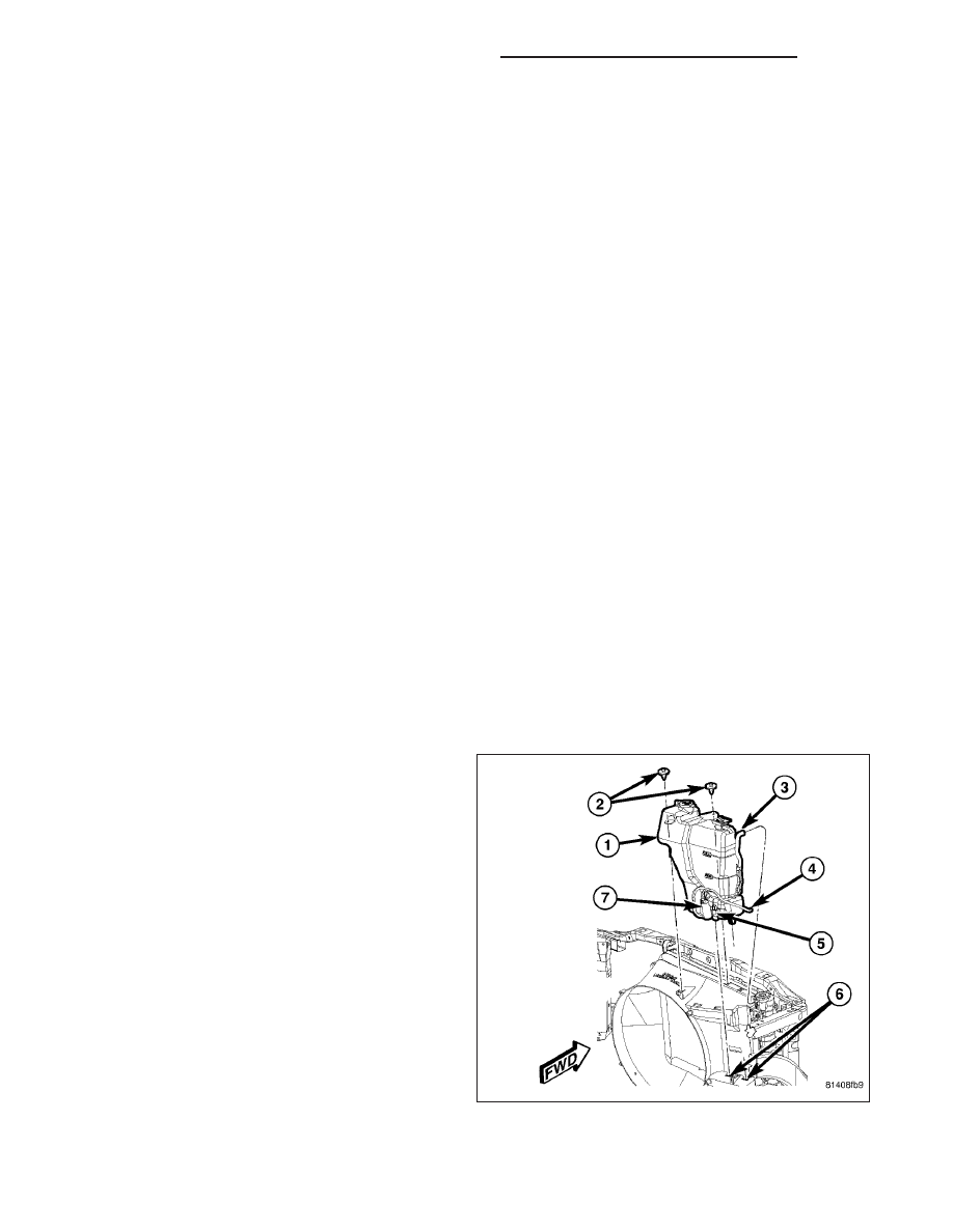
3. Disconnect the coolant overflow hose (3) from the
nipple on the radiator filler neck. It is not necessary
to open or drain the engine cooling system. (Refer
to 7 - COOLING/ENGINE/COOLANT RECOVERY
CONTAINER - REMOVAL).
4. Disconnect the reservoir washer hose (4) from the
barbed nipple of the inline fitting at the engine com-
partment washer hose in the right headlamp and
dash wire harness and allow the washer fluid to
drain from the reservoir into a clean container for
reuse.
5. Disconnect the right headlamp and dash wire har-
ness connector for the washer fluid level switch
from the switch connector receptacle (5).
6. Disconnect the right headlamp and dash wire har-
ness connector for the washer pump/motor unit
from the motor connector receptacle (7).
7. Remove the two screws (2) that secure the reservoir mounting brackets to the top of the radiator shroud.
8. Grasp the bottom of the washer reservoir (1) firmly with both hands and pull the unit sharply upward to disen-
gage the locking feature on the washer reservoir from the depression in the radiator shroud.
8R - 64
WIPERS/WASHERS - SERVICE INFORMATION
DR/DH