Dodge Ram Truck 1500-2500-3500. Manual - part 604
 

  Index      Dodge     Dodge Ram Truck 1500-2500-3500 - service repair manual 2005 year


Search            


Content   ..  602  603  604  605   ..


Dodge Ram Truck 1500-2500-3500. Manual - part 604


1. Unlatch and open the hood.

2. Disconnect and isolate the battery negative cable.

3. Disconnect the washer hose (4) from the barbed

outlet nipple of the washer pump/motor unit (3) and
allow the washer fluid to drain into a clean con-
tainer for reuse.

4. Disconnect the left headlamp and dash wire har-

ness (1) connector for the washer fluid level switch
(5) from the switch connector receptacle.

NOTE: The pivoting float of the washer fluid level
switch must be in a horizontal position within the
reservoir in order to be removed. With the reser-
voir empty and in an upright position, the pivoting
float will orient itself to the horizontal position
when the switch connector receptacle is pointed
straight upwards.

5. Using a trim stick or another suitable wide flat-

bladed tool, gently pry the barbed nipple of the
washer fluid level switch out of the rubber grommet
seal in the washer reservoir sump (2). Care must
be taken not to damage the reservoir.

6. Remove the washer fluid level switch from the washer reservoir.

7. Remove the rubber grommet seal from the washer fluid level switch mounting hole in the washer reservoir and

discard.

INSTALLATION

EXCEPT SRT-10 OR DIESEL ENGINE

1. Install a new rubber grommet seal into the washer

fluid level switch mounting hole in the washer res-
ervoir (2). Always use a new rubber grommet seal
on the reservoir.

2. Insert the float of the washer fluid level switch (3)

through the rubber grommet seal and into the
washer reservoir. The connector receptacle of the
washer fluid level switch should be pointed upward.

3. Using hand pressure, press firmly and evenly on

the washer fluid level switch mounting flange until
the barbed nipple is fully seated in the rubber
grommet seal in the washer reservoir mounting
hole.

4. Reconnect the right headlamp and dash wire har-

ness (4) connector for the washer fluid level switch
to the switch connector receptacle.

5. Reconnect the removed washer hose (1) to the barbed outlet nipple of the washer pump/motor unit (5).

6. Refill the washer reservoir with the washer fluid drained from the reservoir during the removal procedure.

7. Reconnect the battery negative cable.

8. Close and latch the hood.

8R - 56

WIPERS/WASHERS - SERVICE INFORMATION

DR/DH

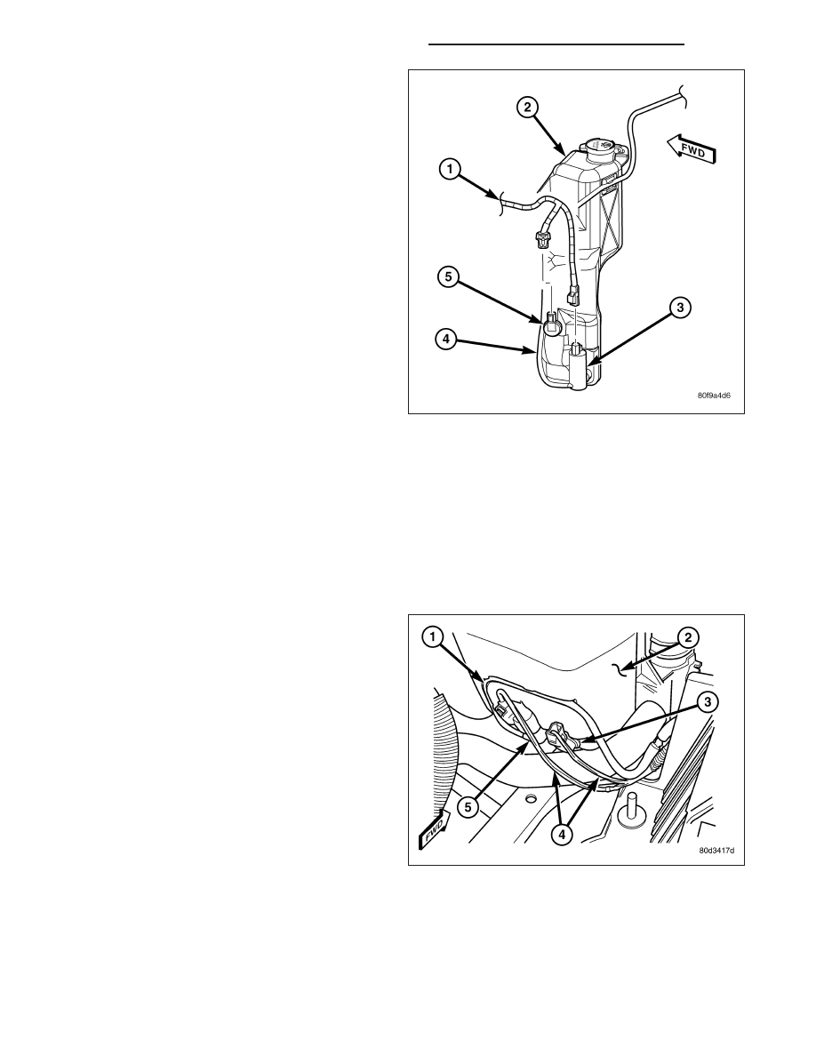
SRT-10 OR DIESEL ENGINE ONLY

1. Install a new rubber grommet seal into the washer

fluid level switch mounting hole in the washer res-
ervoir (2). Always use a new rubber grommet seal
on the reservoir.

2. Insert the float of the washer fluid level switch (5)

through the rubber grommet seal and into the
washer reservoir. The connector receptacle of the
washer fluid level switch should be pointed upward.

3. Using hand pressure, press firmly and evenly on

the washer fluid level switch mounting flange until
the barbed nipple is fully seated in the rubber
grommet seal in the washer reservoir mounting
hole.

4. Reconnect the left headlamp and dash wire har-

ness (1) connector for the washer fluid level switch
to the switch connector receptacle.

5. Reconnect the removed washer hose (4) to the

barbed outlet nipple of the washer pump/motor unit
(3).

6. Refill the washer reservoir with the washer fluid

drained from the reservoir during the removal pro-
cedure.

7. Reconnect the battery negative cable.

8. Close and latch the hood.

WASHER HOSES/TUBES

DESCRIPTION

The washer plumbing consists of a small diameter
rubber reservoir washer hose that is routed from the
barbed outlet nipple of the electric washer pump/motor
unit on the washer reservoir through a trough molded
into the back of the reservoir above the washer pump
to the engine compartment washer hose to the right
side of the engine cooling module. On SRT-10 models
or those equipped with an optional diesel engine, the
reservoir washer hose is routed through routing clips
on the top of the radiator fan shroud from the washer
reservoir on the left side of the radiator to the engine
compartment washer hose on the right side of the
radiator.

The engine compartment washer hose is contained within the right headlamp and dash wire harness (2), which is
routed through the engine compartment along the top of the right front fender wheel house to the dash panel. This
hose is connected to the washer reservoir washer hose at one end (5) and to the cowl plenum washer hose at the
other end (3) with molded plastic in-line fittings that have a barbed nipple on each end.

The cowl plenum washer hose (4) is routed from the engine compartment into the cowl plenum area through a
trough formation located near the right end of the cowl plenum cover/grille panel. The cowl plenum washer hose is

DR/DH

WIPERS/WASHERS - SERVICE INFORMATION

8R - 57

connected to the washer system check valve/wye fitting on the underside of the cowl plenum cover/grille panel. The
cowl plenum washer hose and the two washer nozzle hoses are routed through integral routing clips on the under-
side of the cowl plenum cover/grille panel. The cowl plenum washer hose is connected to one nipple on the wye
fitting and the two washer nozzle hoses are connected to the other two nipples. The washer nozzle hoses are then
routed along the underside of the cowl plenum cover/grille panel to the two washer nozzles.

Washer hose is available for service only as roll stock, which must then be cut to length. The molded plastic washer
hose fittings cannot be repaired. If these fittings are faulty or damaged, they must be replaced.

OPERATION

Washer fluid in the washer reservoir is pressurized and fed by the washer pump/motor through the washer system
plumbing and fittings to the two washer nozzles. Whenever routing the washer hose or a wire harness containing a
washer hose, it must be routed away from hot, sharp, or moving parts; and, sharp bends that might pinch the hose
must be avoided.

WASHER NOZZLE

DESCRIPTION

The fluidic washer nozzles (1) are constructed of
molded plastic. Each nozzle has two integral latches
(2) and an anti-rotation tab (4) that secure them in
dedicated holes in the cowl plenum cover/grille panel
located near the base of the windshield The domed
upper surface of the washer nozzle is visible on the
top of the plenum cover/grille panel, and the nozzle
orifice (5) is oriented towards the windshield glass.
The washer plumbing fittings (3) for the washer noz-
zles extend below the cowl plenum cover/grille panel.
The cowl plenum cover/grille panel must be removed
from the vehicle to access the nozzles for service. The
washer nozzles cannot be adjusted or repaired. If
faulty or damaged, they must be replaced.

OPERATION

The two washer nozzles are designed to dispense washer fluid into the wiper pattern area on the outside of the
windshield glass. Pressurized washer fluid is fed to each nozzle from the washer reservoir by the washer pump/
motor unit through a single hose, which is attached to a barbed nipple on each washer nozzle below the cowl
plenum cover/grille panel. A fluidic matrix within the washer nozzle causes the pressurized washer fluid to be emit-
ted from the nozzle orifice as an oscillating stream to more effectively cover a larger area of the glass to be
cleaned.

8R - 58

WIPERS/WASHERS - SERVICE INFORMATION

DR/DH

REMOVAL

1. Remove both wiper arms from the wiper pivots.

(Refer to 8 - ELECTRICAL/WIPERS/WASHERS/
WIPER ARM - REMOVAL).

2. Unlatch and open the hood.

3. Remove the cowl plenum cover/grille panel from

over the cowl plenum. (Refer to 23 - BODY/EXTE-
RIOR/COWL GRILLE - REMOVAL).

4. From the underside of the cowl plenum cover/grille

panel (1), disconnect the washer nozzle hose from
the barbed nipple (3) of the washer nozzle.

5. From the underside of the cowl plenum cover/grille

panel, release the integral latch features (2) of the
washer nozzle and push the nozzle out through the
mounting hole toward the top side of the cowl ple-
num cover/grille panel.

6. Remove the washer nozzle from the top of the

cowl plenum cover/grille panel.

INSTALLATION

1. From the top of the cowl plenum cover/grille panel,

position the nipple end of the washer nozzle
through the mounting hole and engage the anti-ro-
tation tabs (2 and 4) of the nozzle into the anti-ro-
tation notches in the mounting hole.

2. Using hand pressure, push firmly and evenly on

the top of the washer nozzle until the integral latch
features (6) lock into place on the underside of the
cowl plenum cover/grille panel (1).

3. From the underside of the cowl plenum cover/grille

panel, reconnect the washer hose to the barbed
nipple (3) of the washer nozzle.

4. Reinstall the washer nozzle hose into its routing

clips on the underside of the cowl plenum cover/
grille panel.

5. Reinstall the cowl plenum cover/grille panel over

the cowl plenum. (Refer to 23 - BODY/EXTERIOR/COWL GRILLE - INSTALLATION).

6. Close and latch the hood.

7. Reinstall both wiper arms onto the wiper pivots. (Refer to 8 - ELECTRICAL/WIPERS/WASHERS/WIPER ARM -

INSTALLATION).

DR/DH

WIPERS/WASHERS - SERVICE INFORMATION

8R - 59


Content   ..  602  603  604  605   ..