Dodge Ram Truck 1500-2500-3500. Manual - part 389
INSTALLATION
WARNING: To avoid personal injury or death, on vehicles equipped with airbags, disable the supplemental
restraint system before attempting any steering wheel, steering column, airbag, seat belt tensioner, impact
sensor, or instrument panel component diagnosis or service. Disconnect and isolate the battery negative
(ground) cable, then wait two minutes for the system capacitor to discharge before performing further diag-
nosis or service. This is the only sure way to disable the supplemental restraint system. Failure to take the
proper precautions could result in accidental airbag deployment.
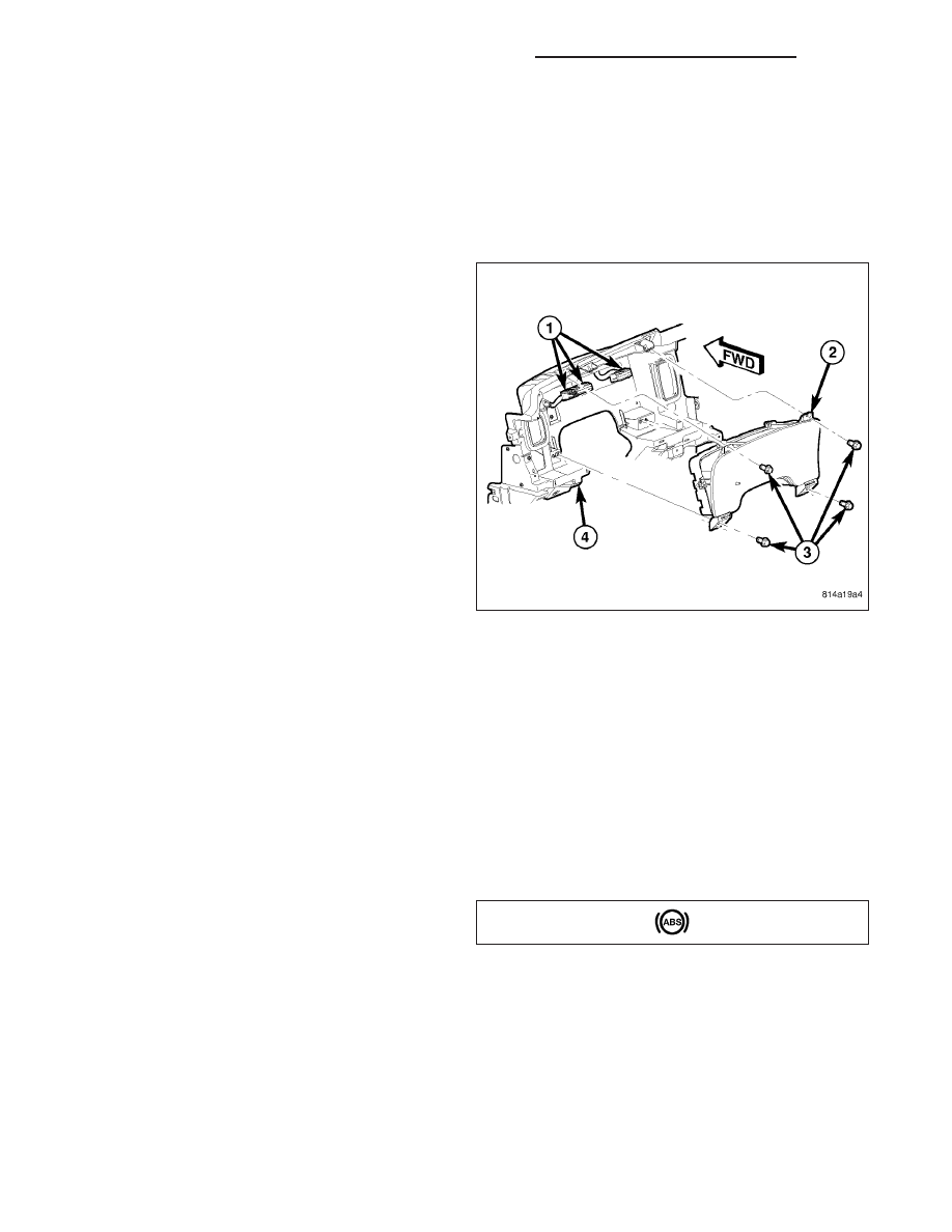
1. Position the instrument cluster close enough to the
instrument panel to reconnect the three instrument
panel wire harness connectors (1) to the connector
receptacles on the back of the cluster housing (2).
2. Position the instrument cluster into the instrument
panel (4).
3. Install and tighten the four screws (3) that secure
the instrument cluster to the instrument panel struc-
tural support. Tighten the screws to 4 N·m (31 in.
lbs.).
4. Reinstall the cluster bezel onto the instrument
panel. (Refer to 23 - BODY/INSTRUMENT PANEL/
CLUSTER BEZEL - INSTALLATION).
5. Reconnect the battery negative cable.
NOTE: Certain indicators in this instrument cluster
are automatically configured. This feature allows
those indicators to be activated or deactivated for
compatibility with certain optional equipment. If a
problem is noted that involves improper illumination of the cruise indicator, the electronic throttle control
indicator, the service four-wheel drive indicator, the tow/haul indicator, the transmission overtemp indicator,
the upshift indicator, the security indicator or the gear selector indicator, disconnect and isolate the battery
negative cable. After about five minutes, reconnect the battery negative cable and turn the ignition switch to
the On position. The instrument cluster should automatically relearn the equipment in the vehicle and prop-
erly configure the configurable indicators accordingly.
ABS INDICATOR
DESCRIPTION
An Antilock Brake System (ABS) indicator is standard
equipment on all instrument clusters. However, the
instrument cluster can be programmed to disable this
indicator on vehicles that are not equipped with the
ABS or Rear Wheel Anti-Lock (RWAL) brake systems, which are not available in some markets. On vehicles
equipped with a gasoline engine, the ABS indicator is located near the lower edge of the instrument cluster,
between the tachometer and the speedometer. On vehicles equipped with a diesel engine, the ABS indicator is
located on the right side of the instrument cluster, to the right of the engine temperature gauge.
The ABS indicator consists of a stencil-like cutout of the International Control and Display Symbol icon for “Failure
of Anti-lock Braking System” in the opaque layer of the instrument cluster overlay. The dark outer layer of the over-
lay prevents the indicator from being clearly visible when it is not illuminated. An amber Light Emitting Diode (LED)
behind the cutout in the opaque layer of the overlay causes the icon to appear in amber through the translucent
outer layer of the overlay when the indicator is illuminated from behind by the LED, which is soldered onto the
instrument cluster electronic circuit board. The ABS indicator is serviced as a unit with the instrument cluster.
8J - 116
INSTRUMENT CLUSTER -SERVICE INFORMATION
DR/DH